16
ENGLISH
1. GÉNÉRAL
Assembly and installation should only be carried out by qualified per-
sonnel.
1.1 Application
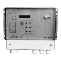
The pump control is designed for fluid level control. It controls and
monitors one (YN3112) or two (YN 3212) pumps with a power input of
up to 4 kW.
For use in potentially explosive areas, the applicable regulations
must be followed.
The switchgear series YN3000 is not explosion-proof and may only be
used outside potentially explosive areas.
1.2 Pr
oduct data
• Operating voltage
YN3112 T4, YN 3212 T4 : 3 ~ 400 V (L1, L2, L3, PE)
YN3112M, YN 3212 M
: 1 ~ 230 V (L, N, PE)
• Frequency : 50/60 Hz
• Control voltage : 230 V AC
• Max. connected power : P2
≤ 4 Kw
•
Current consumption range : 0.3 -12,0A (M) / 0.3-10A (T4)
• Protection : IP 65
• Temperature range : from -20 °C to +60 °C
• Alarm contact : contact load
250 V, 1 A
2. SAFETY
These instructions contain important information which must be follo-
wed when installing and operating the device. It is therefore impera-
tive that they be read by both the installer and the operator before
the device is installed or operated. Both the general safety points in
this section and the more specific safety points in the following sec-
tions should be noted.
2.1 Instruction symbols used in this operating manual
Safety precautions in these operating instructions which, if not
followed, could cause personal injury.
Safety precautions warning of danger due to electricity.
Used to indicate that by ignoring the relevant safe-
ty instr
uctions
, damage could be caused to the
machinery and its functions.
2.2 Staff training
The per
sonnel installing the pump m
ust hav
e the a
ppropriate qualifi-
cations for this work.
2.3 Risks incurred by failure to comply with the safety precautions
Failure to comply with the safety precautions could result in personal
injury or damage to the installation. Failure to comply with the safety
precautions could also invalidate any claim for damages.
In par
ticular
, f
ailure to comply with these safety precautions could
give rise, for example, to the following risks :
- The failure of important functions of the installation.
- Personal injury due to electrical, mechanical and bacteriological
causes.
2.4 Safety considerations for the operator
The relevant accident precaution regulations must be observed.
Potential dangers caused by electrical energy must be excluded.
2.5 Safety considera
tions for inspection and assembly
The oper
ator is responsible for ensuring that inspection and assembly
ar
e carr
ied out b
y author
ised and qualif
ied personnel who have stu-
died the operating instructions closely.
Work on the installation should only be carried out after the machine
h
as been switched off.
2.6 Unauthorised modification and manufacture of spare parts
Alterations to the control box may only be carried out with the
Salmson consent. The use of original spare parts and accessories
authorised by the manufacturer will ensure safety. The use of any
other parts may invalidate claims invoking the liability of Pompes
Salmson for any consequences.
2.7 Improper use
The operating safety of the equipment delivered is only guaranteed
f
or proper usage as detailed in Section 1 of the operating instructions.
Under no circumstances should the limit values given in the data
sheet be exceeded.
3. TRANSPORT AND INTERIM STORAGE
When receiving the material, check that there has been no damage
during the transport. If any defect has been stated, take the required
steps with the carrier within the allowed time.
The switchgear must be protected against moistu-
re and mechanical damage as a result of shocks
or impacts. It may not be exposed to temperatures outside the range
-20°C to +60°C.
4. PRODUCTS AND ACCESSORIES
4.1 Description (See FIG. 1 - 2)
FIG. 1 - Float switch
FIG. 2 - Level sensor IPAE (0-1 mCW)
Swichting levels :
A - Base load OFF
: determines the switch-off point of the first pump.
B - Base load ON : determines the switch-on point of the first pump.
C - Peak load OFF : determines the switch-off point of the second
pump.
D - Peak load ON : determines the switch-on point of the second
pump.
(the value should be equal to or greater than base load OFF).
E - Maxim
um w
a
ter level
: a Maxim
um W
ater Level alarm is genera-
ted when this value is exceeded.
• The water level is recorded electrically by means of float switches
(
See FIG
. 1
).
Up to 4 f
loat switches can be connected. The switch-on and switch-
off points are determined by the arrangement of the float switches in
the shaft. Also fewer float switches can be used.
The contacts for
unassigned le
vel connections must remain free.
• The water level is recorded electrically by means of an external
le
v
el sensor (0-1 mCW) (
See FIG
. 2
) (4-20 mA, tw
o-wir
e technique).
Explosion pr
otection only via saf
ety barrier
(accessory).
The exter
nal sensor con
v
er
ts the le
v
el into an electrical signal (4-20 mA).
The electr
onic control system
YN3000 allo
ws automatic operation of
the system.
The control system basically consists of a microcontroller unit (CPU)
for the control, monitoring, recording and setting of all operating
sequences
.
The pumps ar
e switched via contactors. A built-in Electronic
Ov
er
curr
ent Cir
cuit Breaker protects the pump against overloading.
ATTENTION !
A
TTENTION !
ATTENTION !
 Loading...