The EC-Drain LS2 is an electronic control unit with an integrated microcontroller, designed for the automatic control of two pumps with a maximum power consumption of P2 ≤ 4.0 kW. It is suitable for use in lifting units and with submersible pumps.
Function Description:
The primary function of the EC-Drain LS2 is to control two pumps based on the switching status of connected float switches. When a high water level is reached, the unit emits an acoustic and optical alarm, and the pumps are forced to operate. Both the general fault indication and the high water alarm are activated. If an optional battery (accessory) is installed, a continuous acoustic alarm can be received even in the event of a power failure. The unit also records and evaluates pump faults. Operating statuses are indicated by LEDs on the front panel, and controls are managed via pushbuttons on the right side of the housing. The unit is supplied with a main switch. For the single-phase current version (1~230 V), an integrated service capacitor is included.
Upon reconnection to the power supply or after a power outage, the unit returns to its previously set operating mode. All LEDs activate for approximately 2 seconds for a self-check, after which the unit is ready for operation.
Usage Features:
- Main Switch (3-pole):
0 → OFF: Disables the unit.I → ON: Enables the unit.
- Pushbuttons:
- Manual Operation (pos. 1): When pressed, both Pump 1 and Pump 2 operate, regardless of float switch signals. All safety functions, such as electronic motor protection and winding protection contact control, remain active. The green LEDs for "Pump 1 Operation" (pos. 6) or "Pump 2 Operation" (pos. 10) illuminate while the pumps are active. This function is intended for commissioning or test operation. Manual mode is only active as long as the button is pressed.
- Stop (pos. 2): Pressing the Stop button deactivates automatic operation for both pumps, and the green LEDs (pos. 5, pos. 9) flash. The pumps will not start automatically. If a high water level is reached, an acoustic and optical alarm is triggered, and both the general fault contact and the high water alarm contact are activated.
- Automatic Operation (pos. 3): When pressed, automatic operation is activated for both pumps, based on the DIP switch settings (DIP 6 and 7, Fig. 2, pos. 3). The green LEDs (pos. 5, pos. 9) illuminate continuously. If a pump has been deactivated via DIP switches, its corresponding LED remains off. In automatic mode, pumps operate according to float switch signals. When the first start level is reached, the float switch closes, and the main pump starts. When the second start level is reached, the standby pump starts. The green LEDs (pos. 6, pos. 10) illuminate while the pumps are running. If the stop level is reached, the float switch opens, the standby pump stops, and the main pump's adjusted post-run time (set via potentiometer, Fig. 2, pos. 2) begins. The green LEDs (pos. 6, pos. 10) flash during the post-run time, after which the main pump stops. To optimize operating times, the main pump alternates after each shutdown. All safety functions, including electronic motor protection and winding protection contact control, are active in automatic mode. In case of a pump fault, the unit automatically switches to the operational pump, an optical and acoustic alarm is triggered, and the general fault contact (SSM) is activated. If a high water level is reached, an optical and acoustic alarm is triggered, and both the general fault contact (SSM) and high water alarm contact are activated. Additionally, the pumps are forced to operate to enhance system safety.
- Buzzer Off/Reset (pos. 4): In case of a fault, the integrated buzzer emits an acoustic signal. Briefly pressing this button silences the buzzer and acknowledges the fault relay. To confirm the fault and reset the control unit, the button must be held for at least half a second. Resetting is only possible after the fault and its cause have been resolved.
- Fault Memory: The control unit has a fault memory.
- Simultaneously pressing "stop" + "auto" displays the last stored fault (refer to Section 10 Faults, Causes, and Remedies).
- Simultaneously pressing "Manual 1" + "stop" clears the fault memory.
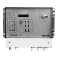
- Display Elements (Fig. 1):
- Ready for Operation (pos. 15): Green LED illuminates continuously when power is supplied and control voltage is present.
- Automatic Operation (pos. 5, pos. 9): Green LED flashes if control voltage is present but automatic operation is deactivated. It illuminates continuously when automatic operation is active. It does not flash if the pump is deactivated via a DIP switch.
- Operation (pos. 6, pos. 10): Green LED illuminates when the pump is running (start level reached). It flashes green if the pump continues to run beyond the adjusted post-run time.
- High Water Level (pos. 14): Red LED illuminates when the high water alarm is triggered.
- Overload Fault (pos. 7, pos. 11): Red LED illuminates if the electronic overcurrent release is triggered. Setting is done via DIP switches (Section 6.2.3). It flashes red if the control unit operates without a load.
- Winding Fault (pos. 8, pos. 12): Red LED illuminates if the winding protection contact (WSK) is triggered.
- Service (pos. 13): Yellow LED illuminates to indicate that a service interval set via DIP switches (Fig. 2, pos. 3) has expired. It flashes yellow if the control unit is operating without a load. For increased operational safety, maintenance is recommended. The counter must be reset by qualified personnel.
- System Parameters Exceeded (pos. 13): Yellow LED flashes if one of the following system parameters is exceeded: pump starts per hour, pump starts per day, pump run time per hour. These values are permanently programmed and cannot be changed. If a signal is output, it is recommended to check the system or operating conditions. The counter must be reset by qualified personnel.
- Incorrect Phase Sequence (only for three-phase operation): If the phase sequence is incorrect, all LEDs flash sequentially in an anti-clockwise direction. An acoustic alarm is triggered, and the general fault contact (SSM) is activated.
- DIP Switches (Fig. 2, pos. 1) above the potentiometer:
- Internal Electronic Motor Protection (DIP 1-5): To protect the motor from overload, the electronic overcurrent release must be set via DIP switches 1 to 5 (1.5-12 A) according to the pump's nominal current. Disconnection occurs if the set nominal pump current is exceeded, or if the current drops below 300 mA for 1 second while the pump is running. Disconnection follows a software-defined tripping curve. After each overcurrent trip, the fault must be confirmed with the reset button. If DIP switches 1 to 5 are OFF, the minimum current value of 1.5 A is set. If one or more DIP switches are ON, their corresponding values are added to the base value of 1.5 A.
- Pump Test Run (DIP 6): To prevent long idle times, a cyclical test run function is provided. This function is activated (ON) or deactivated (OFF) via DIP switch 6. A test run lasts 2 seconds after a 24-hour pump idle time.
- Buzzer (DIP 7): The internal buzzer is activated (ON) or deactivated (OFF) via DIP switch 7. If there is a power failure or the main switch is off, the buzzer cannot be deactivated via the DIP switch. In such cases, the battery (accessory) must be removed from its holder.
- DIP Switches (Fig. 2, pos. 3) below the potentiometer:
- Maximum System Parameters (DIP 1-3): To prevent potential overload and premature system failure, DIP switches 1 to 3 can be activated (ON). When activated, the software monitors that the preset system parameters are maintained. Functions can be activated individually or together. If factory preset values are exceeded, an optical signal is output via the yellow LED (Fig. 1, pos. 13). No acoustic alarm is triggered, and the general fault contact (SSM) is not active. If an optical signal is output, it is recommended to check the system and operating conditions. The counter must be reset by qualified personnel.
- Service (DIP 4-5): The system service interval can be set via DIP switches 4 and 5. If both DIP switches are deactivated (OFF), no service indication appears. If the set service interval expires, an optical signal is output via the yellow LED (Fig. 1, pos. 13). No acoustic alarm is triggered, and the general fault contact (SSM) is not active. For increased operational safety, maintenance is recommended when the optical signal appears. The counter must be reset by qualified personnel. The service interval is continuously recorded when the mains voltage is applied.
- Pump Activation (DIP 6-7): DIP switches 6 and 7 select the pump operating mode. Each pump can be deactivated (OFF) or activated (ON). The green LED (Fig. 1, pos. 5, pos. 9) indicates the status. Note: If deactivated, the pump will not be switched on by the float switch, even if required.
- Post-Run Time (Fig. 2, pos. 2): This is the time from when the float switch contact opens until the base pump switches off. The post-run time is set via the potentiometer on the unit, continuously adjustable from 0 to 30 seconds.
- External WSK Motor Protection: If the motor has a winding protection contact (WSK), it must be connected to terminals 1 and 2 for Pump 1, and terminals 3 and 4 for Pump 2. For motors without a WSK contact, a wire bridge must be installed.
- High Water Alarm: To enable the high water alarm, a float switch must be connected to terminals 9 and 10 (HW). When triggered, an optical and acoustic alarm is emitted, and the pump is forced to operate. Both the general fault contact (SSM) and the high water alarm are active.
Important Technical Specifications:
- Power Supply Voltage: 1~230 V (L, N, PE) or 3~400 V (L1, L2, L3, PE)
- Frequency: 50/60 Hz
- Max. Switching Power: P2 ≤ 4 kW, AC 3
- Max. Current: 12 A
- Protection Type: IP 54
- Max. Mains Fuse Protection:
- 16 A, slow-blow (with pre-assembled 1.5 mm² cable for 1~)
- 25 A, slow-blow (with direct terminal connection)
- Ambient Temperature: -20 to +60 °C
- Alarm Contact: Max. contact load 250 V~, 1 A
- Housing Material: ABS
- Housing Dimensions (LxWxH): 289 mm x 239 mm x 107 mm
- Electrical Safety: Degree of pollution II
Maintenance Features:
Maintenance and repair work must only be carried out by qualified personnel. During all maintenance and repair work, the system must be disconnected from the mains voltage and secured against unauthorized reconnection. Damaged connection cables must be repaired by a qualified electrician.
For control units used in wastewater lifting systems, maintenance must be performed by qualified personnel according to EN 12056-4. Maintenance intervals should not exceed:
- ½ year for industrial systems
- 1½ years for multi-family homes
- 1 year for single-family homes
The system operator must ensure that all maintenance, inspection, and installation work is carried out by authorized and qualified personnel who have thoroughly studied the installation and operating instructions. A visual inspection of electrical components is required. Establishing a maintenance plan helps avoid costly repairs and ensures fault-free operation with minimal investment. A protocol should be kept for completed maintenance.
Troubleshooting:
Faults must only be remedied by qualified personnel.
- Red LED illuminates (Overcurrent):
- Cause: Electronic overcurrent release triggered.
- Remedy: Check pump and DIP switch settings. After resolving the fault, reset the LED display with the Reset button (Fig. 1b, pos. 4).
- Red LED flashes (Undercurrent/Phase Failure):
- Cause: Pump current below 300 mA or phase L2 missing.
- Remedy: Check power supply, pump, and pump cable. After resolving the fault, reset the LED display with the Reset button (Fig. 1b, pos. 4).
- Red LED illuminates (WSK Triggered):
- Cause: WSK winding protection contact triggered or bridge on WSK terminals missing.
- Remedy: Check pump and wiring.
- Red LED illuminates (High Water Alarm):
- Cause: High water alarm signal.
- Remedy: Check system/pump.
- All LEDs flash sequentially anti-clockwise (Incorrect Phase Sequence):
- Cause: Incorrect phase sequence.
- Remedy: Refer to the direction of rotation check under Section 8 Commissioning.
If operating faults cannot be remedied, consult a specialist technician or the nearest Salmson sales service point or representative.
Spare Parts:
Spare parts are ordered via Salmson's after-sales service. To avoid queries and incorrect orders, all data on the nameplate should be submitted with each order. Subject to change without prior notice.