ENGLISH
16
7. INSTALLATION AND ELECTRICAL CONNECTION
DANGER! Risk of fatal injury!
Inappropriate installation or electrical connection can
be life-threatening.
•The installation and electrical connection may only be
carried out by qualified personnel in accordance with
the applicable regulations!
•Observe the regulations for accident prevention.
7.1 Installation
Install the switchgear in a dry, vibration-free and frost-safe
location.
Protect the place of installation from direct sunlight.
Borehole distances 268 x 188 mm (WxH). For more information,
see also bottom side of switchgear. For fastening, provide
screws (4 screws, Ø max 4 mm) and the corresponding dowels.
To fasten the switchgear, open the upper part of the housing:
•Loosen the 4 cover fixing screws
•Fasten the switchgear to the wall with the dowels and screws.
7.2 Electrical connection
DANGER! Risk of fatal injury!
Improper electrical connections can lead to fatal elec-
trical shocks.
Only allow the electrical connection to be made by an
electrician approved by the local electricity supply
company and in accordance with the local regulations
in force.
•The type of mains, current and voltage of the mains connec-
tion must match the details on the type plate of the pump/
motor.
•Mains requirements:
NOTE: In accordance with DIN EN/IEC 61000-3-11 (see
table below), the switchgear and pump with motor
power of ... kW (column 1) are provided for operation
on a mains power supply with a system impedance of
Z
max
at the house connection of max. ... Ohm (column
2) for a maximum number of ... switchings (column 3).
If the mains impedance and the number of switching
operations per hour is greater than the values given in
the table, because of the unfavourable mains connec-
tions, the switchgear with the pump may lead to tem-
porary voltage drops and also to disturbing voltage
fluctuations, or flickering.
Therefore, measures may be necessary before the
switchgear with pump can be operated correctly on
this connection. The necessary information must be
obtained from the local electricity supply company
and the manufacturer.
•Mains side fuse protection:
– max. 16 A, slow-blow (with premounted cable 1.5 mm² for
1~)
– max. 25 A, slow-blow (with direct power supply to terminal)
•To increase operating safety, it is essential that a circuit breaker
(which disconnects all power leads) with K characteristic is
used. Provide residual-current-operated protection switch in
accordance with the regulations in force.
•Feed the ends of the pump cable through the cable screw fit-
tings and cable inlets and wire them according to the mar-
kings on the terminal strip.
•Earth the pump/installation according to regulations.
•The terminal strip is to be connected as follows:
Mains connection 1~230 V (L, N, PE):
Terminals 2/T1, N, PE
Connection to the main switch at the terminals 2/T1 and N
according to the wiring diagram (Fig. 2). The grounding con-
ductor is connected to the remaining PE terminal.
Mains connection 3~400 V (L1, L2, L3, PE):
Terminals 2/T1, 4/T2, 6/T3, PE
Connection to the main switch at the terminals 2/T1, 4/T2 and
6/T3 according to the wiring diagram (Fig. 2). The grounding
conductor is connected to the remaining PE terminal.
Motor contactor (terminals 2/T1, 4/T2, 6/T3)
The pumps are connected directly to the motor contactor at
the terminals 2/T1, 4/T2 and 6/T3 according to the wiring dia-
gram (Fig. 2). The grounding conductor is connected to the
remaining PE terminal.
SSM (terminals 11, 12, 13):
Connection for external collective fault signal, potential-free
changeover contact,
•min. contact load 12 V DC, 10 mA,
•max. contact load 250 V~, 1A,
e.g. for connecting a horn, flashing light or alarm switchgear
(at potential-free input).
The contact is closed between terminals 12 and 13 in the event
of an alarm, when the voltage fails, or when the main switch is
switched off.
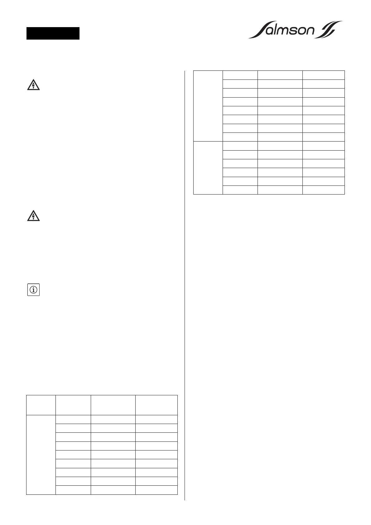
Output [kW]
(column 1)
System
impedance [Ω]
(column 2)
Switchings per
hour
(column 3)
3~400 V 2.2 0.2788 6
2-pole 3.0 0.2000 6
4.0 0.1559 6
2.2 0.2126 24
3.0 0.1292 24
4.0 0.0889 24
2.2 0.1915 30
3.0 0.1164 30
4.0 0.0801 30
3~400 V 3.0 0.2090 6
4-pole 4.0 0.1480 6
2.2 0.2330 24
3.0 0.1380 24
4.0 0.0830 24
2.2 0.2100 30
3.0 0.1240 30
4.0 0.0740 30
1~230 V 1.5 0.4180 6
2-pole 2.2 0.2790 6
1.5 0.3020 24
2.2 0.1650 24
1.5 0.2720 30
2.2 0.1480 30