Do you have a question about the Salus RT310TX and is the answer not in the manual?
Provides essential safety precautions for installation and usage, including warnings.
Provides guidelines and diagrams for the optimal placement of the thermostat.
Step-by-step instructions for mounting the thermostat onto a wall.
Guides through the initial setup process after inserting batteries.
Explains the function of the switches located on the RXRT510 receiver.
Illustrates how to connect the thermostat and receiver to the heating system.
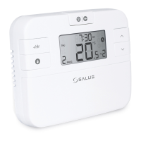
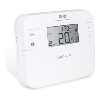
The RT310RF thermostat is a wireless room thermostat designed to simplify the control of heating systems. It operates by sensing the ambient air temperature and switching the heating system on or off as needed. When the room temperature falls below the user-defined setpoint, the thermostat activates the heating; once the set temperature is reached, it switches the heating off. This intelligent control helps maintain a comfortable environment while optimizing energy consumption.
A key principle of using this thermostat effectively is to find the lowest temperature setting that provides comfort and then leave it undisturbed. Adjusting the thermostat to a higher setting will not accelerate the heating process, as the speed at which a room heats up depends on the heating system's design (e.g., boiler size, radiator capacity). Similarly, it doesn't affect how quickly the room cools down. Setting a lower temperature results in the room being controlled at a lower temperature, leading to energy savings. The recommended approach is to start with a low temperature, such as 18°C, and gradually increase it by one degree each day until a comfortable level is achieved. Further adjustments beyond this point would lead to wasted energy and increased costs.
For heating systems with a boiler and radiators, a single room thermostat typically controls the entire house. However, individual room temperatures can be managed by installing thermostatic radiator valves (TRVs) on radiators. If TRVs are not present, users should select a temperature suitable for the whole house. With TRVs, a slightly higher setting can be chosen to ensure comfort in the coldest room, while TRVs prevent overheating in other areas.
For accurate temperature sensing, room thermostats require a free flow of air and should not be obstructed by curtains or furniture. Nearby heat sources like electric fires, televisions, or lamps can also interfere with the thermostat's proper functioning.
The RT310RF thermostat offers several advantages:
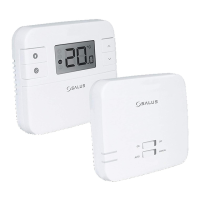
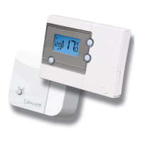
The system consists of two main components: the RT310TX thermostat (transmitter) and the RXRT510 receiver. The receiver is powered by 230VAC and has a maximum load capacity of 16A. It should be installed in a location free from direct exposure to water, moisture, or air condensation. The RXRT510 receiver can operate in two modes: AUTO (automatic) and MANUAL. These modes are selected using switches on the receiver's front panel. For the receiver to function with the thermostat, its switches must be set to the ON / AUTO position.
The receiver's status is indicated by two LEDs: a red (upper) LED and a green (lower) LED.
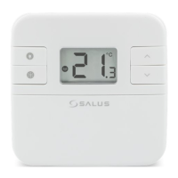
In manual mode, the thermostat maintains a constant temperature set by the user. To adjust the setpoint, the thermostat first displays the actual room temperature. Users can then press the UP or DOWN buttons to set the new desired temperature. After a 2-second timeout, the changes are approved, and the thermostat returns to displaying the room temperature.
This mode automatically sets a frost setpoint temperature to prevent pipes from freezing. If the room temperature drops below this setpoint, frost protection activates. To enable/disable frost protection, press the snowflake button. The snowflake icon will appear on the display when frost protection is active. The frost setpoint temperature can be viewed by pressing the UP button once, but it can only be changed in Installer Mode. Frost protection is only available in HEAT mode.
Sleep mode switches off the thermostat, conserving energy. No actions can be performed while in this mode. To activate sleep mode, simultaneously press and hold the UP and DOWN buttons for 3 seconds. The thermostat's display will go blank. To deactivate sleep mode, press any button, and the thermostat will return to its main screen.
Users can configure the thermostat for either heating or cooling. In HEAT mode, a flame icon is displayed. If the thermostat is calling for heat, the flame icon flashes. In COOL mode, a snowflake icon is displayed. If the thermostat is calling for cooling, the snowflake icon flashes. The default mode is HEAT. Note that there may be a delay of approximately 3 minutes when the thermostat needs to initiate a call for cooling. To set COOLING mode: While in HEATING mode (flame icon displayed), press and hold the snowflake button for 5 seconds. The snowflake icon will then be steady ON. If the thermostat is calling for COOL, the snowflake icon will flash. To set HEATING mode: While in COOLING mode (snowflake icon displayed), press and hold the snowflake button for 5 seconds. The flame icon will then be steady ON. If the thermostat is calling for HEAT, the flame icon will flash.
Temperatures below 10°C are displayed without a leading '0'. Temperatures exceeding the measurable range are indicated by 'HI' for temperatures above the upper limit, and 'LO' for temperatures below the lower limit.
The battery voltage is checked every minute. When the battery level drops, a Low-Battery warning indicator appears. The thermostat will continue to function normally, but it is recommended to replace the batteries as soon as possible to ensure uninterrupted operation. When changing batteries, users have approximately 30 seconds to do so without losing their settings.
To access installer parameters, simultaneously press and hold the UP, DOWN, and snowflake buttons for about 3 seconds. Once in installer mode, use the snowflake button to navigate through parameters and the UP or DOWN buttons for adjustments. Confirm each change or selection by pressing the snowflake button. Installer parameters include temperature display accuracy, temperature offset, and frost protection setpoint temperature.
DIP switches, located under the back cover of the thermostat, are used to set the control algorithm. The position of these switches determines the type of control algorithm, such as Hysteresis or TPI (Time Proportional and Integral). TPI algorithm is recommended for underfloor heating and can be adjusted between a low comfort level (6 CPH) and a higher comfort level (9 CPH). "CPH" refers to cycles per hour, indicating the frequency of measurement cycles performed by the thermostat.
The RT310RF set comes factory-paired. However, if re-pairing is necessary, ensure the receiver is disconnected from the power supply and its switches are in the AUTO and ON positions. Reconnect the receiver to the power supply and wait for the red diode to glow continuously. Then, quickly move the top switch to the OFF position and back to ON. The red LED will start blinking, confirming the receiver has entered pairing mode. On the thermostat, press and hold the TEST / PAIRING button for 3 seconds. The thermostat will begin the pairing process, which can take up to 9 minutes. Once the red diode on the receiver lights up continuously, the devices are paired on a new frequency. To exit pairing mode on the thermostat, press and hold the TEST / PAIRING button for 3 seconds again. The thermostat will return to the main screen, indicating successful pairing.
To test the radio signal connection, it's important to place the receiver and transmitter in locations free from interference. The communication range in an open area is up to 60m, but factors like thick walls, aluminum foil, metal objects, and general radio interference can shorten this distance. It's advisable to test the radio transmission before mounting the thermostat on the wall, which can be done by changing the set temperature to activate or deactivate heating. To initiate the test, press the TEST / PAIRING button on the thermostat for 1 second. An antenna icon will appear on the display, and the red and green LEDs on the receiver will begin to flash. The test mode can last up to 9 minutes. To return to the main screen, press the TEST / PAIRING button again. The receiver will then revert to normal operating mode.
To reset the RT310TX thermostat, remove the batteries without pressing any buttons. Wait 2 minutes, then reinsert the batteries. The device will restart. The thermostat uses internal memory to back up settings when batteries are changed, providing a 30-second window to replace them without losing configurations.
The RT310RF thermostat requires minimal maintenance. Periodically, the outer casing can be wiped clean with a dry cloth. Avoid using solvents, polishes, detergents, or abrasive cleaners, as these can damage the thermostat. The unit contains no user-serviceable parts; any servicing or repairs should only be performed by Salus Controls or their authorized agents.
| Type | Wireless Thermostat |
|---|---|
| Frequency | 868 MHz |
| Power Supply | 2 x AA batteries |
| Display | LCD |
| Mounting | Wall-mounted |
| Communication | Wireless |
| Temperature Control Accuracy | ±0.5°C |