EasyManua.ls Logo

Salus RT510BC+ - User Manual

Salus RT510BC+
2 pages
Print Icon
To Next Page IconTo Next Page
Loading...
TEST / PAIRING
SELECT
+Hr
SET
i
Once paired please close the
boiler control panel.
The LED will start flashing red.
TEST / PAIRING
+Hr
SELECT SET
RXBC605 Installation
RXBC605 Wiring Terminals
RXBC605
1
3
6
2
5
4
Remove the front panel from the boiler.
Do not remove boiler loop.
Replace the front panel ensuring a good seal is made.
Connect the electrical plug.
Pull out the mechanical timer.
Push fit boiler control into housing.
7 Power up the boiler and check the correct operation.
Quick Guide
RT510BC+
Always isolate the AC Mains supply before installing or working on any components
that require 230 VAC 50Hz supply.
RT510BC+ (Thermostat) Button Functions
Introduction
The RT510BC+ thermostat will switch your heating system on or o, as needed, in accordance
with the time and temperature set by you. It can be used with the RXBC605 integral plug-in RF
boiler control. The RF boiler control is a direct replacement for the basic time clock or blanking
plate usually supplied with the boiler. Installing the RF boiler control takes minutes. Once
installed, you will benefit from all the control features of the RT510BC+ thermostat.
868.0-868.6MHz; <13dBm
Safety Information
Use in accordance with the regulations. Indoor use only. Keep your device completely dry. Disconnect
your device before cleaning it with a dry cloth. This accessory must be tted by a competent person, and
installation must comply with the guidance, standards and regulations applicable to the city, country or
state where the product is installed. Failure to comply with the relevant standards could lead to prosecution.
Product Compliance
This product complies with the essential requirements and other relevant provisions of the following EU Directives: EMC
2014/30/EU, LVD 2014/35/EU, RED 2014/53/EU and RoHS 2011/65/EU. Full text of the EU Declaration of Conformity is
available on www.saluslegal.com
+Hr
SELECT
SELECT
SET
SET
+
+
+
Key Function
1. Press once to activate Frost Mode
2. Press for 3 seconds in order to activate Holiday Mode
Press once to activate/deactivate Boost function
Press once to enter/exit Permanent Override function
Increase button
Decrease button
Select the clock or programme settings
Press to conrm your settings
1. Press once to enter/exit in Test Mode
2. Press for 3 seconds to enter/exit Pairing Mode
Press the buttons for 3 seconds to enter Installer Mode
Press the buttons for 3 seconds to enter Clock Settings
Box content
Quick Guide
2 x AA Alkaline
Batteries
2 x Fixing Screws
RT510BC+
Desk Stand
TEST / PAIRING
SELECT
+Hr
SET
i
Once paired please close the
boiler control panel.
The LED will start flashing red.
TEST / PAIRING
+Hr
SELECT SET
RXBC605 Installation
RXBC605 Wiring Terminals
RXBC605
1
3
6
2
5
4
Remove the front panel from the boiler.
Do not remove boiler loop.
Replace the front panel ensuring a good seal is made.
Connect the electrical plug.
Pull out the mechanical timer.
Push fit boiler control into housing.
7 Power up the boiler and check the correct operation.
Quick Guide
RT510BC
Always isolate the AC Mains supply before installing or working on any components
that require 230 VAC 50Hz supply.
RT510TX Button Functions
Introduction
The RT510TX thermostat will switch your heating system on or o, as needed, in accordance
with the time and temperature set by you. It can be used with the RXBC605 integral plug-in RF
boiler control. The RF boiler control is a direct replacement for the basic time clock or blanking
plate usually supplied with the boiler. Installing the RF boiler control takes minutes. Once
installed, you will benefit from all the control features of the RT510TX thermostat.
868.0-868.6MHz; <13dBm
Safety Information
Use in accordance with the regulations. Indoor use only. Keep your device completely dry. Disconnect
your device before cleaning it with a dry cloth. This accessory must be tted by a competent person, and
installation must comply with the guidance, standards and regulations applicable to the city, country or
state where the product is installed. Failure to comply with the relevant standards could lead to prosecution.
Product Compliance
This product complies with the essential requirements and other relevant provisions of the following EU Directives: EMC
2014/30/EU, LVD 2014/35/EU, RED 2014/53/EU and RoHS 2011/65/EU. Full text of the EU Declaration of Conformity is
available on www.saluslegal.com
+Hr
SELECT
SELECT
SET
SET
+
+
+
Key Function
1. Press once to activate Frost Mode
2. Press for 3 seconds in order to activate Holiday Mode
Press once to activate/deactivate Boost function
Press once to enter/exit Permanent Override function
Increase button
Decrease button
Select the clock or programme settings
Press to conrm your settings
1. Press once to enter/exit in Test Mode
2. Press for 3 seconds to enter/exit Pairing Mode
Press the buttons for 3 seconds to enter Installer Mode
Press the buttons for 3 seconds to enter Clock Settings
Box content
Quick Guide
2 x AA Alkaline
Batteries
2 x Fixing Screws
RT510TX
Desk Stand
RT510TX Dip Switch Settings
The DIP Switches can be found on the rear of your thermostat.
Control feature TPI Span
Operation When TPI is selected on DIP
switch № 2, the DIP switch
№ 1 is functional. You can
choose the Cycles Per Hour
between a lower comfort
level (6CPH) and a higher
comfort level (9CPH).
When Span is selected
on DIP switch № 2,
the DIP switch № 1 is
not functional. The
temperature accuracy of
your thermostat is set to
± 0.25 °C.
TEST / PAIRING
SELECT
+Hr
SET
TEST / PAIRING
SELECT
+Hr
SET
3 Sec
TEST / PAIRING
+Hr
SELECT SET
3
4
Test the Pairing Process
Pairing Process
Once the LED stops flashing, press the
TEST / PAIRING button for 3 sec.
1
2
Begin the pairing process
End the pairing process
i
i
i
During test pairing, boiler control should ash conrming pair. If not, please follow
Pairing Process.
When enter test pairing
mode, after a 10 minute
countdown the thermostat
will time out.
Terminal Identier Description
1 N Neutral
2 L Live input (230V AC)
3 COM Common terminal (volt free)
4 N.O. Normally Open
RXBC605 User Controls
RXBC605 Switch Position
LED - It will be on when the thermostat is demanding
heat.
Mode Switch
The AUTO / MANUAL switch allows you to turn on the
Boiler Control manually if required.
SYNC Button - This is used only for pairing the RF
communications.
Press the SYNC button for 3
seconds until LED starts ashing.
The LG+5V is ready to be paired
with your thermostat.
3 Sec
2. MANUAL mode. The user
can also move the switch to the
MANUAL position; when in this
mode, the boiler will be always turned
on and the LED indicator will also
be lit constantly. The manual mode
is only to be used as a temporary
control if problems develop with the
communication from the thermostat.
1. AUTO mode. When the switch
on the Boiler Control is in the AUTO
(normal) position, the Boiler Control
will automatically receive the RF signal
from the transmitter and control the
boiler based on the programming of
the transmitter.
1 2
When the thermostat is operating in
NORMAL mode, if the Boiler Control has
not received a signal from the transmitter
after 1 hour, the Boiler Control will turn
off the boiler, and the LED indicator will
flash constantly (two times every second).
Once the Boiler Control receives a valid
ON or OFF signal, the Boiler Control will
control the heating system accordingly.
SALUS Controls plc
SALUS House
Dodworth Business Park South,
Whinby Road, Dodworth,
Barnsley S75 3SP, UK.
T: +44 (0) 1226 323961
E: sales@salus-tech.com
E: techsupport@salus-tech.com
SALUS Controls is a member of the Computime Group.
Maintaining a policy of continuous product development SALUS Controls plc reserve the right to
change specification, design and materials of products listed in this brochure without prior notice.
www.salus-tech.com
Issue Date: February 2018
V005
For PDF Installation guide please go to www.salus-manuals.com
TEST / PAIRING
SELECT
+Hr
SET
3 Sec
RT510BC+ (Thermostat) Dip Switch Settings
TEST / PAIRING
SELECT
+Hr
SET
TEST / PAIRING
SELECT
+Hr
SET
3 Sec
TEST / PAIRING
+Hr
SELECT SET
3
4
Test the Pairing Process
Pairing Process
Once the red LED on your receiver stops
flashing, press the TEST / PAIRING
button for 3 sec.
1
2
Begin the pairing process
End the pairing process
i
i
i
During test pairing, boiler control should ash conrming pair. If not, please follow
Pairing Process.
When enter test pairing
mode, after a 10 minute
countdown the thermostat
will time out.
Terminal Identier Description
1 N Neutral
2 L Live input (230V AC)
3 COM Common terminal (volt free)
4 N.O. Normally Open(volt free)
RXBC605 User Controls
RXBC605 Switch Position
LED - It will be on when the thermostat is demanding
heat.
Mode Switch
The AUTO / MANUAL switch allows you to turn on the
Boiler Control manually if required.
SYNC Button - This is used only for pairing the RF
communications.
Press the SYNC button for 3
seconds until LED starts ashing.
The LG+5V is ready to be paired
with your thermostat.
3 Sec
2. MANUAL mode. The user
can also move the switch to the
MANUAL position; when in this
mode, the boiler will be always turned
on and the LED indicator will also
be lit constantly. The manual mode
is only to be used as a temporary
control if problems develop with the
communication from the thermostat.
1. AUTO mode. When the switch
on the Boiler Control is in the AUTO
(normal) position, the Boiler Control
will automatically receive the RF signal
from the transmitter and control the
boiler based on the programming of
the transmitter.
1 2
When the thermostat is operating in
NORMAL mode, if the Boiler Control has
not received a signal from the transmitter
after 1 hour, the Boiler Control will turn
off the boiler, and the LED indicator will
flash constantly (two times every second).
Once the Boiler Control receives a valid
ON or OFF signal, the Boiler Control will
control the heating system accordingly.
SALUS Controls plc
SALUS House
Dodworth Business Park South,
Whinby Road, Dodworth,
Barnsley S75 3SP, UK.
T: +44 (0) 1226 323961
E: sales@salus-tech.com
E: techsupport@salus-tech.com
SALUS Controls is a member of the Computime Group.
Maintaining a policy of continuous product development SALUS Controls plc reserve the right to
change specification, design and materials of products listed in this brochure without prior notice.
www.salus-tech.com
For PDF Installation guide please go to www.salus-manuals.com
Issue Date: Sept 2019
V011
TEST / PAIRING
SELECT
+Hr
SET
3 Sec
Boiler
PLUS
C
O
M
P
L
I
A
N
T
Internal Temperature
Load Compensation
ITLC
The DIP Switches can be found on the rear of your thermostat.
For all plug-in boiler receiver applications ensure SW1 is set to RAD.
Control feature ITLC SPAN
Operation When ITLC is selected on DIP
switch № 2, the DIP switch №
1 is functional. You can choose
between radiator or electric
heater.
When Span is selected
on DIP switch № 2, the
DIP switch № 1 is not
functional.
ON
1
2
ON
ELEC
SPAN 0.5 °C
(±0.25 °C)
RAD ITLC
Question and Answer IconNeed help?

Do you have a question about the Salus RT510BC+ and is the answer not in the manual?

Summary

RXBC605 User Controls

LED Indicator

Indicates when the thermostat is demanding heat.

SYNC Button

Used for pairing the RF communications.

Mode Switch

Allows manual control of the boiler if needed.

RXBC605 Installation

Remove Front Panel and Timer

Steps to remove the boiler's front panel and mechanical timer.

Connect Boiler Control

Connect the electrical plug and insert the boiler control.

Power Up and Check Operation

Power up the boiler and verify correct operation.

RXBC605 Wiring Terminals

Test the Pairing Process

Pairing Process Steps

Guide for pairing the thermostat with the boiler control receiver.

RT510 BC+ Button Functions

RT510 BC+ Dip Switch Settings

Introduction and Compliance

Product Compliance

Declaration of conformity with EU directives for the product.

Safety Information

Important safety precautions for installation and use.

RXBC605 Switch Position

AUTO Mode

Boiler control receives RF signal from thermostat for automatic operation.

MANUAL Mode

User can manually turn the boiler on; LED indicator stays lit.

Setting Time and Date

Permanent Override

Holiday Mode

Programming Options

5-2 Days Programme

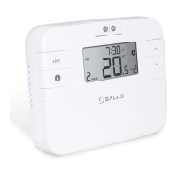
Allows personalized programming for weekdays and weekends.

24 h Programme

Enables 24-hour programming with 6 sets of time/channel.

Review Setpoint Temperature

Boost Function

Frost Protection

Temporary Override

Installer Mode

Reset and Battery Replacement

Reset Function

Procedure to reset the thermostat by removing batteries.

Changing Batteries; Blank Screen

Instructions for battery replacement to avoid blank screen issues.

Overview

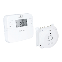
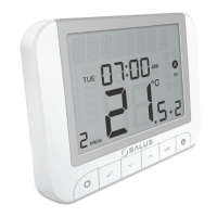
This document describes the Salus RT510BC+ thermostat and its associated RXBC605 RF boiler control, providing comprehensive instructions for installation, operation, and maintenance. The system is designed to manage heating systems efficiently by allowing users to set specific time and temperature schedules.

Function Description

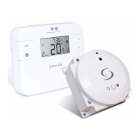
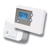
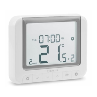
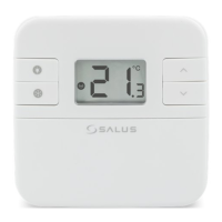
The Salus RT510BC+ is a programmable thermostat that controls your heating system based on user-defined time and temperature settings. It communicates wirelessly with the RXBC605 RF boiler control, which acts as a direct replacement for a standard time clock or blanking plate on your boiler. This wireless communication enables flexible placement of the thermostat within your home.

The thermostat features an Internal Temperature Load Compensation (ITLC) function, which helps optimize heating performance by considering the internal temperature of the room. This ensures more precise temperature control and potentially greater energy efficiency.

The RXBC605 boiler control has two operational modes:

  • AUTO mode: In this mode, the boiler control automatically receives RF signals from the thermostat and regulates the boiler according to the thermostat's programmed schedule. This is the normal operating mode for automated heating.
  • MANUAL mode: This mode allows the user to manually turn the boiler on, causing the LED indicator on the boiler control to light up constantly. This mode is intended for temporary control, particularly if there are communication issues with the thermostat, ensuring heating can still be provided.

A key safety feature is the boiler control's behavior in NORMAL mode: if it does not receive a signal from the thermostat for one hour, it will turn off the boiler, and its LED indicator will flash constantly (twice per second). The boiler will resume normal operation once a valid ON or OFF signal is received from the thermostat.

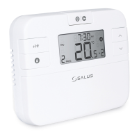
The RT510BC+ thermostat includes several button functions for various operations:

  • Frost Mode: Activates a low-temperature protection setting to prevent pipes from freezing.
  • Holiday Mode: Allows users to set a specific period during which the heating system will maintain a lower temperature, conserving energy while away.
  • Boost Function: Provides a temporary increase in heating for a set duration and temperature, useful for quickly warming a room.
  • Permanent Override: Enables a continuous temperature setting that overrides the programmed schedule until manually deactivated.
  • Increase/Decrease Buttons: Used for adjusting temperature, time, and other settings.
  • SELECT/SET Buttons: Used for confirming selections and navigating menus.
  • Installer Mode: Accessible by pressing specific buttons simultaneously, this mode allows for advanced configuration of parameters such as temperature display increments, temperature offset, frost protection setpoint, and programmer selection (5/2 days or 24 hours).
  • Pairing Mode: Initiates the process to establish wireless communication between the thermostat and the boiler control.

The thermostat also features DIP switches on its rear for advanced configuration:

  • ITLC (Internal Temperature Load Compensation): When selected, DIP switch 1 allows users to choose between radiator or electric heater control, adapting the thermostat's behavior to the specific heating system.
  • SPAN: When selected, DIP switch 1 is not functional, indicating a different control characteristic.

Usage Features

The RT510BC+ system is designed for ease of use, offering intuitive programming and control options.

Installation: The RXBC605 boiler control is designed for straightforward installation. It involves removing the existing front panel and mechanical timer from the boiler, connecting the electrical plug, and then pushing the boiler control into the housing. It's crucial to ensure a good seal when replacing the front panel. The installation process is quick, often taking only minutes, and requires basic electrical connections (Neutral, Live input, Common, Normally Open). Safety information emphasizes isolating the AC Mains supply before installation and ensuring compliance with local regulations.

Pairing Process: Establishing wireless communication between the thermostat and the boiler control is simple. The user presses the SYNC button on the boiler control for 3 seconds until its LED flashes red. Simultaneously, the thermostat is put into pairing mode. Once paired, the red LED on the receiver stops flashing, indicating successful communication.

Setting Time and Date: The thermostat allows users to set the current time and date, including the hour format (e.g., 12-hour or 24-hour). This is crucial for accurate scheduling of heating programs.

Programming: Users can create personalized heating programs. The system offers two main programming options:

  • 5-2 Days Programme: This allows for separate schedules for weekdays (5 days) and weekends (2 days), with 6 time/temperature settings per day, totaling 12 settings per week.
  • 24h Programme: This provides a daily schedule with 6 time/temperature settings per day, totaling 42 settings per week. Users can review and adjust setpoint temperatures for each programmed period.

Override Functions:

  • Permanent Override: This feature allows users to set a continuous temperature that overrides the programmed schedule. It's useful for extended periods when a consistent temperature is desired, such as during a cold spell.
  • Temporary Override: This allows for a temporary adjustment of the setpoint temperature without altering the main program.

Holiday Mode: This feature enables users to set a specific duration (in days) during which the heating system will maintain a lower, energy-saving temperature. This is ideal for when the home is unoccupied for an extended period. The holiday period can be set to zero to exit Holiday Mode.

Boost Function: The boost function provides a quick way to temporarily increase the heating. Users can set the duration and the desired boost temperature, which is useful for rapid warming of a room.

Frost Protection: This essential safety feature maintains a minimum temperature (default 5.0°C, adjustable in Installer Mode) to prevent pipes from freezing, particularly important during colder months or when the property is vacant. The frost protection mode can be activated and deactivated with a single button press.

Installer Mode: This advanced mode allows for customization of several parameters to fine-tune the thermostat's operation:

  • Temperature display increments (d01): Adjusts the precision of temperature display (0.1°C or 0.5°C).
  • Temperature offset (d02): Allows calibration of the displayed temperature if it doesn't match the actual room temperature.
  • Frost Protection setpoint temperature (d03): Sets the minimum temperature for frost protection (5.0°C - 17.0°C).
  • Programmer selection (d04): Switches between 5/2 days or 24-hour programming modes.

Maintenance Features

The RT510BC+ system incorporates features to ensure reliable long-term operation and ease of maintenance.

Battery Management: The thermostat is powered by 2 x AA Alkaline batteries. The device will display a "low battery" symbol when the batteries need replacing.

  • Battery Replacement Procedure: When replacing batteries, it's recommended to remove the old batteries and wait for 5 minutes before inserting new ones if the screen has gone blank due to critically low power. This ensures the internal circuit is fully discharged, preventing potential restart issues.
  • Internal Memory Backup: The thermostat has an internal memory that backs up settings during battery changes. Users have a 30-second window to replace batteries without losing their programmed settings.

Reset Function: If the thermostat experiences issues, a reset function is available. This involves removing the batteries without pressing any buttons, waiting 2 minutes, and then reinserting the batteries. This action restarts the device and can resolve minor operational glitches.

Product Compliance: The device complies with essential EU Directives, including EMC 2014/30/EU, LVD 2014/35/EU, RED 2014/53/EU, and RoHS 2011/65/EU, ensuring it meets safety and environmental standards. The full EU Declaration of Conformity is available online.

Safety Information: Users are reminded to use the device in accordance with regulations, for indoor use only, and to keep it dry. Disconnecting the device before cleaning with a dry cloth is advised. Any installation or work on components requiring 230 VAC 50Hz supply must be performed by a competent person and comply with relevant standards and regulations to prevent prosecution. Always isolate the AC Mains supply before working on such components.

Salus RT510BC+ Specifications

General IconGeneral
Power Supply2 x AA batteries
DisplayLCD
MountingWall Mounted
WirelessYes
Programming7-day programming
CertificationCE
Wireless Protocol868 MHz
CompatibilityBoilers
CommunicationWireless
RangeUp to 30m

Related product manuals