10 | SAMLEX AMERICA INC.
APPENDIX A
SECTION 3 | Operation
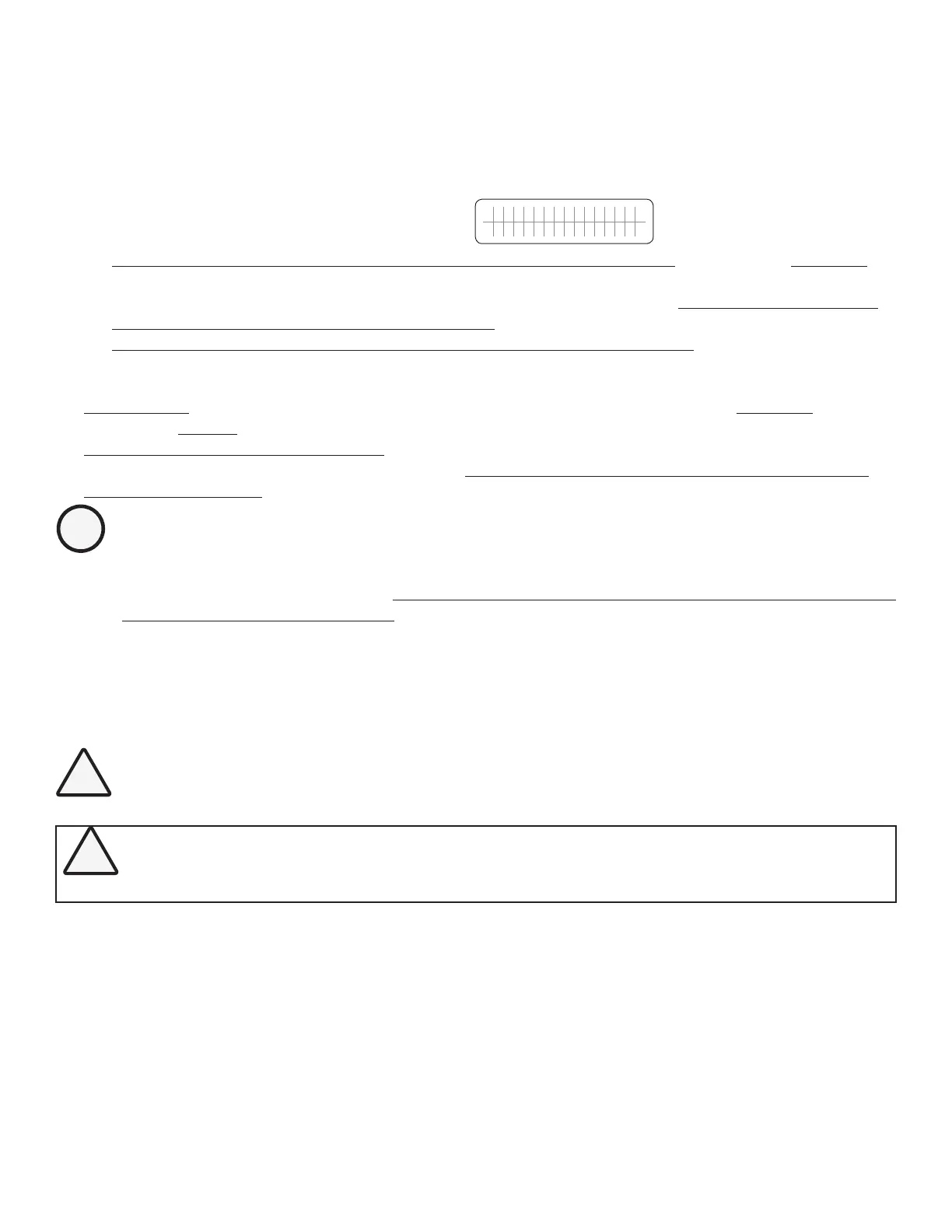
c) On entering Standby Mode, the following will be displayed:
i. On the EVO-RC: The LCD will show the 1
st
screen
S T A N D B Y
B A T T E R Y 1 2 . 0 0 0 V
of the 7 Standby Mode Screens
(See Screens 1 to 7 of screens shown under Group 1, Standby Mode in Fig 3.2) and Status LED (3, Fig 1.1) will
blink once every 5 sec
ii. On the Front Panel of EVO Inverter-Charger: The Green LED marked “ON” (12, Fig 2.1 of the attached
EVO-1212/3012/2224/4024 Inverter Charger Manual) will blink once every 5 sec. Red LED marked “FAULT”
(13, Fig 2.1 of the attached EVO-1212/3012/2224/4024 Inverter-Charger Manual) and Buzzer will be off
3.4.1.2 Exiting Standby Mode: Standby Mode can be exited as follows:
• Using EVO-RC: To exit Standby Mode using Remote Control EVO-RC, press the On/Off Key (2, Fig 1.1)
momentarily (0.1 sec).
• From Front Panel of EVO Inverter Charger: It is NOT POSSIBLE to exit Standby Mode by momentary pressing
of the On/Off Push Button on the front panel of EVO (11, Fig 2.1 of the attached EVO-1212/3012/2224/4024
Inverter Charger Manual) if EVO-RC Remote in NOT connected to EVO.
INFO
Please note that when Standby Mode is exited, EVO Inverter-Charger Unit will execute the programmed
Operating Mode from the beginning. It will NOT start from the last condition of the operating stage it was
in when Standby Mode was activated.
3.5. FAULT MESSAGES & CLEARING FAULTS
If any fault occurs, the LCD screen will display the Fault Message and the Red LED “Fault” will be lighted. Refer to Table
7.1 in Section 7 for details of various fault messages and procedure to clear the fault.
CAUTION!
The cause of the fault should be removed before the unit is restarted.
ATTENTION!
La cause de la panne doit être retiré avant un redémarrage de l'appareil.
3.6 OPERATING MODES AND ASSOCIATED LCD DISPLAY SCREENS
3.6.1 Menu Maps for Operating Mode Screens
When the unit is operating normally, the LCD Screen will display the name of the Operating Mode and values of various
associated operating parameters. As all the operating parameters associated with a particular Operating Mode cannot
be displayed in one screen, multiple screens are available that can be accessed by scrolling the screens using the Up and
Down Keys. For ease of navigating through the various screens, all the screens covering a particular Operating Mode
have been arranged in the associated Menu Map. Table 3.1 shows the names of the Operating Modes and the Fig Nos.
of the associated Menu Maps.