Version with digital positioner
WARNING!
Directly after connecting the voltage to the
actuator, a zero calibration is automatically
performed when the absolute travel adjust
-
ment is set (state of delivery), causing the
actuator stem to move.
Do not touch the actuator stem or obstruct it
to avoid risk of injury to hands or fingers.
NOTICE
During zero calibration, the control valve
moves through a part of the travel range.
As a result, do not connect the wires of the
actuator while a process is running. Instead,
close the shut-off valves in the plant first.
Connect the 6-wire cable according to
Fig. 4.
12 EB 5867 EN
Combination with Type 5857 Electric Actuator
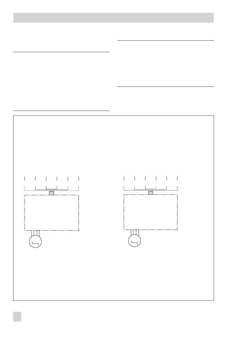
Fig. 4 · Electrical connection – Version with digital positioner
M
24 V AC 0...10 V 0...10 V
_
+
_
+
NL
OG YE RD BK BN GN
For 24 V AC connection
OG orange
YE yellow
RD red
BK black
BN brown
GN green
M
OG YE RD BK BN GN
24 V DC 0...10 V 0...10 V
_
+
_
++
_
For 24 V DC connection
Control
signal
Feedback,
output
Control
signal
Feedback,
output