6 EB 8097 EN
Design and principle of operation
2 Design and principle of oper-
ation
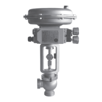
The Type3347 Angle Valve can be com-
bined with either a Type3271 Pneumatic
Actuator or a Type3277 Pneumatic Actuator
with integral positioner attachment.
The standard valve body is designed for
welding into pipelines. Other versions can
be equipped with threaded or anged ends,
or clamp connections.
The control valve is tted with an easily de-
tachable clamp connection between valve
body and bonnet. The body free of dead
space is suitable for CIP (Cleaning-In-Place).
The control valves are mainly designed for
use as control or on/off valves in the food
industry.
The medium ows through the valve in the
direction indicated by the arrow. The plug
(3) is moved by changing the signal pressure
acting on the diaphragm of the actuator.
The plug stem (6) with plug (3) and actuator
stem (8.1) are connected by the stem con-
nector (7) and sealed by a PTFE seals (5.1
and 5.3).
In the special version with steam line connec-
tion, an additional spring-loaded PTFE ring
packing (4.2) is used. In this case, the plug
stem can be cleaned through the connection
of a steam line.
Fail-safe position
Depending on how the compression
springs(8.3) are arranged in the actuator,
the valve has two different fail-safe positions:
− Actuator stem extends: when the signal
pressure is reduced or the air supply
fails, the springs move the actuator stem
downward and close the valve.
The valve opens when the signal pressure
is increased enough to overcome the
force exerted by the springs.
− Actuator stem retracts: when the signal
pressure is reduced or the air supply
fails, the springs move the actuator stem
upward and open the valve.
The valve closes when the signal pressure
is increased enough to overcome the
force exerted by the springs.
Legend for Fig.1
1 Valve body
1.1 Centering ring
1.2 Body gasket
1.3 Compensating ring
3 Plug
4.1 Spring (special version)
4.2 Packing (special version)
4.3 Washers (special version)
5 Valve bonnet
5.1 Stem seal
5.2 Body and stem seal
5.3 Wiper ring
5.4 Clamp
5.5 Travel indicator scale
6 Plug stem
6.1 Stem connector nut
6.2 Lock nut
7 Stem connector
8 Actuator
8.1 Actuator stem
8.2 Ring nut
8.3 Compression springs
9 Signal pressure
connection
10 Compression-type tting

 Loading...