EB 8359-1 EN 19
Operating the positioner
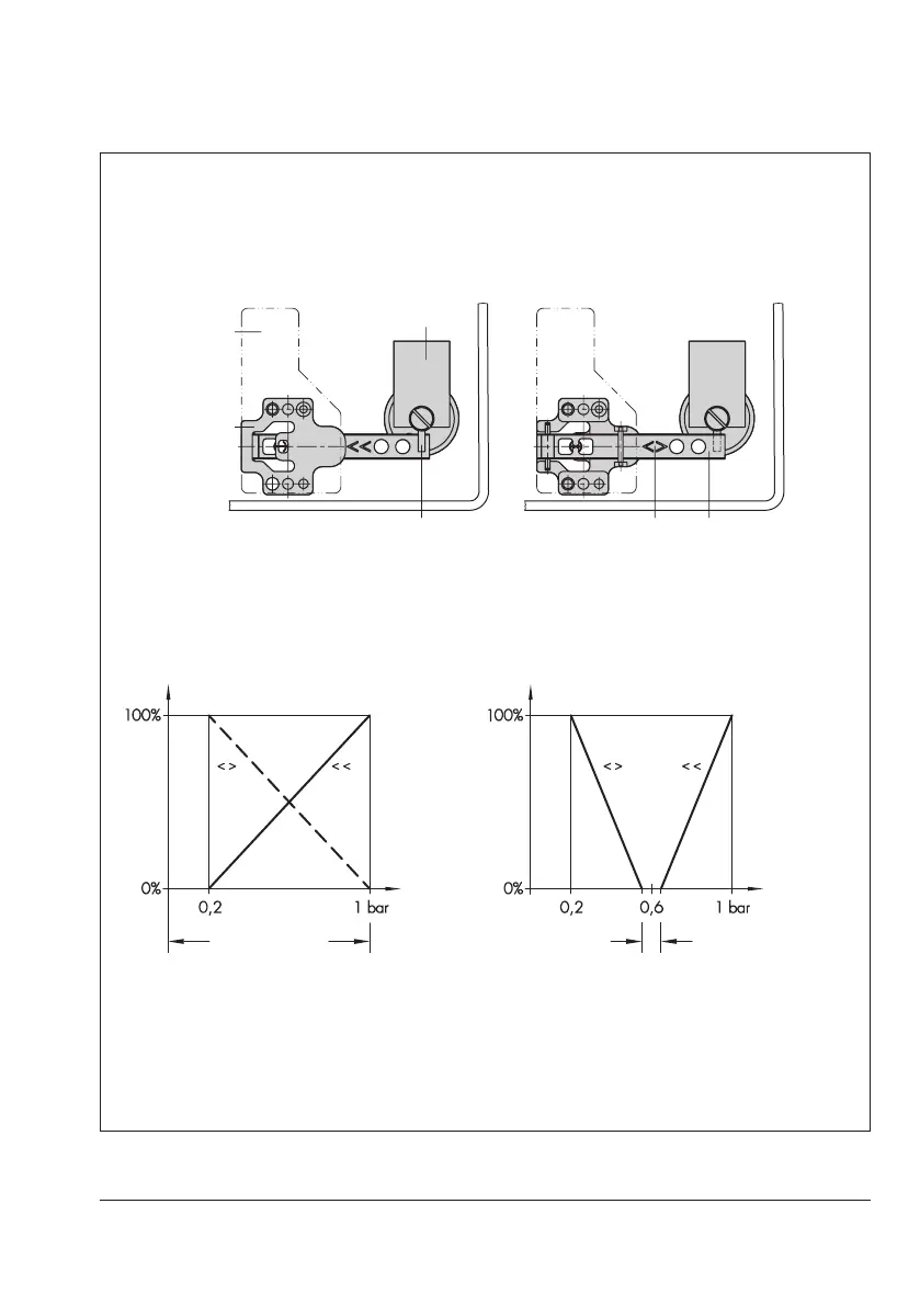
Fig.10: Position of nozzle block, cover plate removed
Fig.11: Normal operation
Fig.12: Split-range operation, two valves operating in
opposing directions
Operating direction increasing/increasing (direct <<)
feeler pin on top of apper plate
Operating direction increasing/decreasing
(reverse <>)
apper plate on top of feeler pin
Range spring
Feeler pin
Cover plate
Nozzle block
Marking Flapper plate
Reference variable
Input signal
Travel
Dead band
Valve 2
Valve 1
Travel