Do you have a question about the Samson AirLine ATX and is the answer not in the manual?
Press and hold for 3 seconds to turn the unit on or off. Quick press mutes/unmutes.
LED displays operation mode, low battery, and recharge status (colors defined).
Press to adjust volume level in 9 steps. Indicator light flashes faster for increase.
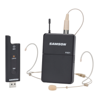
Window captures infrared signal for syncing transmitter and receiver channel.
Magnetic connector for recharging the internal Lithium Ion battery via USB.
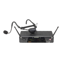
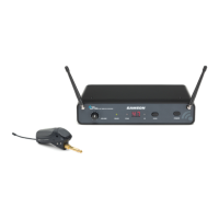
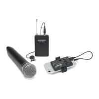
Connects input device via mini-XLR; supplied with lavalier, headset, or instrument mic.
Clip to fasten the ATX transmitter to a belt, waist band, or instrument bell.
Front BNC antenna jacks allow full rotation for optimum placement.
Sets audio signal level output through balanced/unbalanced jacks.
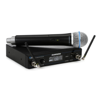
Displays transmitter and receiver settings like group, channel, and frequency.
Cycles through groups or scans for channels. Hold to scan.
Cycles through channels or initiates IR Set for syncing transmitter.
Press and hold to turn the CR99 power on and off.
Emits infrared light during 'IR SET' to set the transmitter channel.
Indicates the selected group number.
Indicates the selected channel number.
Shows the operating frequency of the selected group and channel.
Shows which antenna (A or B) is currently active.
Indicates the remaining battery level of the transmitter.
Indicates the strength of the incoming audio signal.
Indicates the strength of the incoming radio signal.
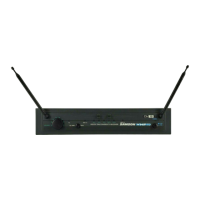
Rear BNC antenna jacks allow full rotation for optimum placement.
Connects the supplied power adapter. Use strain relief to prevent damage.
Electronically balanced low impedance XLR jack for professional audio equipment.
Unbalanced high impedance 1/4" jack for consumer audio equipment.
| RF Power | 10mW |
|---|---|
| Modulation | FM |
| Operating Range | Up to 100 meters (328 feet) |
| Polar Pattern | Cardioid |
| Frequency Response | 50 Hz - 18 kHz |
| Dynamic Range | >100 dB |
| Connector | XLR, 1/4" (Receiver) |