EB 8015 EN 5-3
Installation
− The valve and all valve accessories (in-
cluding piping) are not damaged.
− The valve data on the nameplate (type
designation, nominal size, material,
pressure rating and temperature range)
match the plant conditions (nominal size
and pressure rating of the pipeline, me-
dium temperature etc.). See the 'Mark-
ings on the device' chapter for name-
plate details.
− The requested or required additional
pipe ttings (see section 'Additional t-
tings') have been installed or prepared
as necessary before installing the valve.
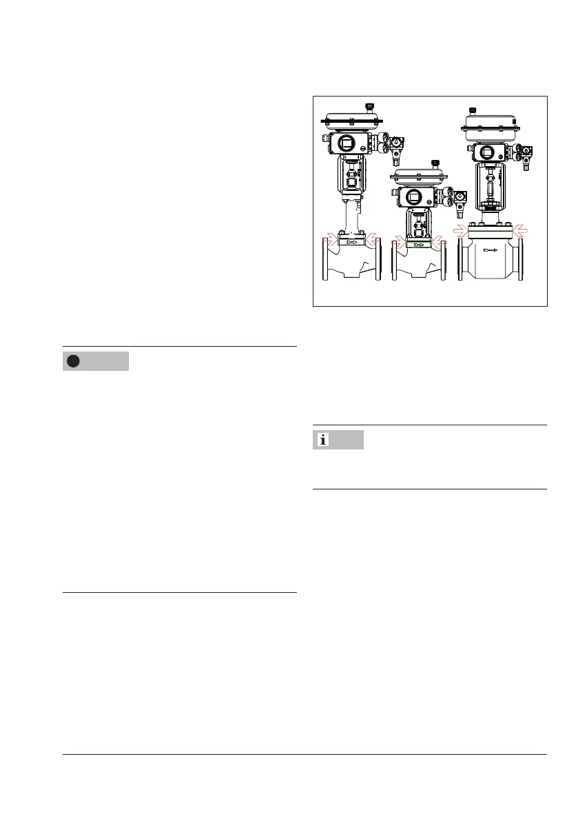
Risk of control valve damage due to incor-
rect insulation.
Î Only insulate control valves up to the
bonnet ange of the valve body (see
Fig.5-1). This also applies to versions
with bellows seal or insulating section at
medium temperatures below 0°C or
above 220°C. If the insulating section is
insulated, it will not function properly.
Î Do not insulate valves mounted to com-
ply with NACE MR0175 requirements
and which have nuts and bolts that are
not suitable for sour gas environments.
Fig.5-1: Limit of insulation for control valves
Proceed as follows:
Î Lay out the necessary material and tools
to have them ready during installation
work.
Î Flush the pipelines.
The plant operator is responsible for clean-
ing the pipelines in the plant.
Î For steam applications, dry the pipelines.
Moisture will damage the inside of the
valve.
Î Check any mounted pressure gauges to
make sure they function properly.
Î When the valve and actuator are deliv-
ered already assembled, check the tight-
ening torques of the bolted joints
(uAB0100). Components may loosen
during transport.
NOTICE
!
Note