POWER
10
11
7
9
8
21
22
GAIN REDUCTION dB INPUT / OUTPUT LEVEL dB
-24 -6 -4-12 -2
-18 0 +6-6 +9
COMPRESSOR / LIMITER CH 3
dB
OFF +10
0
20
TRIGGER
RELEASE
GATE
THRESHOLD
dB
-40 +20
10-30
-10 4:1
dB
62
1
RATIO
I/O
ENHANCER
METER
dB
-20 +20
+10-10
0
OUTPUT
GAIN REDUCTION dB INPUT / OUTPUT LEVEL dB
-24 -6 -4-12 -2
-18 0 +6-6 +9
COMPRESSOR / LIMITER CH 4
dB
OFF +10
050
20
TRIGGER
RELEASE
GATE
THRESHOLD
dB
-40 +20
10-30
-10
4:1
dB
62
1
RATIO
I/O
ENHANCER
METER
dB
-20 +20
+10-10
0
OUTPUT
PANDER/GATE EXPANDER/GATE
IN/OUT 3
STEREO LINK
IN/OUT 4
P
WE
14 THRESHOLD - Used to set minimum signal level at
which the Compressor circuit begins to function.
15 RATIO - Controls the amount Gain Reduction in pro-
portion to the amount of signal over the selected
threshold level.
16 I/O METER SWITCH - Selects either the input or out-
put level to be displayed on the Input/Output meter.
17 ENHANCE SWITCH- Activates S•com 4’s ERF
(Enhanced Frequency Recovery) circuit restoring the
high end loss resulting from extreme Gain Reduction.
18 OUTPUT- Controls the level of output signal.
19 CHANNEL 1 IN/OUT - Activates S•com 4 Channel 1.
20 CHANNEL 2 IN/OUT - Activates S•com 4 Channel 2.
21 CHANNEL 1 IN/OUT - Activates S•com 4 Channel 3.
22 CHANNEL 2 IN/OUT - Activates S•com 4 Channel 4.
.
CH 1
LEVEL
BALANCED
OUTPUT
BALANCED
INPUT
+4
-10
CH 2
LEVEL
BALANCED
OUTPUT
BALANCED
INPUT
+4
-10
3
CED
UT
H I
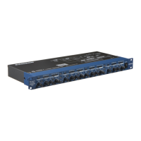
E CHANNEL 4 XLR LINE OUTPUT - XLR Balanced line
output.
F CHANNEL 4 1/4” TRS LINE OUTPUT - 1/4” TRS
Balanced line output.
G CHANNEL 3 - Same Inputs and Outputs as channel 4
H CHANNEL 2 - Same Inputs and Outputs as channel 4
I CHANNEL 1 - Same Inputs and Outputs as channel 4
7
ENGLISH
 Loading...