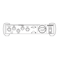
Controls and Functions
1 GATE OPEN & CLOSED LEDS - Indicates when the
gate is open and closed.
2 GATE SWITCH - Selects either Gate or Expander
mode.
3 GAIN REDUCTION METER - Displays the amount of
Gain Reduction when Compressor circuit is activated.
4 INPUT/OUTPUT METER - Displays the Input or
Output signal level based on the setting of the I/O
meter switch.
5 STEREO LINK SWITCH- When engaged channel 2
functions are controlled by the settings on channel 1.
6 CHANNEL 2 CONTROLS - The same knob and switch
complement as channel 1 .
1
2
3
4
5
12
13
15
16
14
17
18
19
20
6
IN/OUT 1
STEREO LINK
IN/OUT 2
GAIN REDUCTION dB INPUT / OUTPUT LEVEL dB
-24 -6 -4-12 -2
-18 0 +6-6 +9
COMPRESSOR / LIMITEREXPANDER/GATE CH 1
dB
OFF +10
050
20
TRIGGER
RELEASE
GATE
THRESHOLD
dB
-40 +20
10-30
-10 4:1
dB
62
1
RATIO
I/O
ENHANCER
METER
dB
-20 +20
+10-10
0
OUTPUT
GAIN REDUCTION dB INPUT / OUTPUT LEVEL dB
-24 -6 -4-12 -2
-18 0 +6-6 +9
COMPRESSOR / LIMITEREXPANDER/GATE CH 2
dB
OFF +10
050
20
TRIGGER
RELEASE
GATE
THRESHOLD
dB
-40 +20
10-30
-10 4:1
dB
62
1
RATIO
I/O
ENHANCER
METER
dB
-20 +20
+10-10
0
OUTPUT
50
T
EX
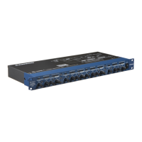
4 CHANNEL
COMPRESSOR
GATE
7 CHANNEL 3 CONTROLS - The same knob and switch
complement as channel 1.
8 STEREO LINK SWITCH (3 & 4)-When engaged, chan-
nel 4 functions are controlled by the settings on chan-
nel 3.
9 CHANNEL 4 CONTROLS - The same knob and switch
complement as channel 1.
10 MAINS POWER SWITCH - When turned on, activates
the S•com.
11 RACK EARS - Used for mounting into a 19inch stan-
dard rack.
12 TRIGGER- Controls the threshold level that the
Expander/Gate becomes activated.
13 RELEASE SWITCH - Selects FAST or SLOW Release
Time for EXPANDER/GATE.
A AC INLET - IEC standard AC power cable connector
with external fuse.
B CHANNEL 4 XLR LINE INPUT - XLR Balanced line
input.
CH 3
LEVEL
BALANCED
OUTPUT
BALANCED
INPUT
+4
-10
CH 4
LEVEL
BALANCED
OUTPUT
BALANCED
INPUT
+4
-10
A
B ED
C F
G
C CHANNEL 4 1/4” TRS LINE INPUT - 1/4” TRS
Balanced line input.
D OPERATING LEVEL SWITCH - Switches the operat-
ing level from -10 to +4.
6
Front Panel Layout
Rear Panel Layout
ENGLISH
 Loading...