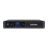
Guided Tour - Front Panel
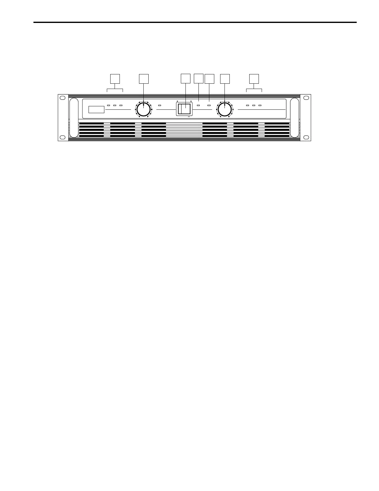
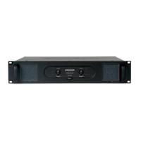
1: Power switch - Use this to power the S500 on or off.
2: Power LED - Lights whenever the S500 is powered on.
3: Protection LED - This goes on for approximately five seconds whenever the S500 is powered on and
then turns off (you’ll hear a “click” when it does so). The Protection LED will also light when overheating
or other severe problems occur (see page 6 in this manual for more information). It is normal for the
Protection LED to fade slowly when the amp is powered off. When lit, 0 volts DC are provided to all con-
nected speakers, thus muting them and preventing any “thump” from occurring. For a complete descrip-
tion of the conditions under which this light goes on, see the section entitled “The S500 Protection
Circuitry” on page 6 of this manual.
4: Channel input level controls - These 42-position detented knobs allow you to precisely adjust the
input level of the signal arriving at the rear-panel input jacks (see #7 on the following page). At their fully
counterclockwise position (labeled “-80 dB”), the signal is attenuated by 80 dB (essentially completely
off). At their fully clockwise position (labeled “0 dB”), the signal is at unity gain (that is, no attenuation).
When 0 dBu of signal arrives at the input jacks and the Channel input level controls are set to their fully
clockwise “0 dB” position, the S500 delivers full power output.
5: LED meters - These three-segment LED meters continuously monitor the power output level for the
corresponding channel. For convenience, the segments are labeled, from left to right, -40 dB, -20 dB,
and CLIP. The left (-40 dB) segment lights whenever input signal is present. The right (CLIP) segment
lights whenever the channel is outputting signal at full strength. For the best signal-to-noise ratio, the
right (CLIP) segment should light occasionally during peak levels; if it lights frequently, you may be
overloading the S500 and a distorted (“clipped”) signal is probably being output. If this occurs and back-
ing off the Input Level control delivers too low an output level for your application, consider using Bridged
mode (see the “Bridged and Parallel Modes” section on page 7 in this manual for more information).
5