Edition May 2018 Quick Guide KA 8493 EN
3 Operation
Turn () the rotary pushbutton to select menu items, parameters,
or values. Press ( ) the button to conrm the setting.
for 2s to go back one level.
Conguration must be enabled before changing parameters:
1.
to return to the main menu.
2. until the 'User level' appears.
3. and until 'On-site: write' appears.
4. to conrm.
Refer to associated mounting and operating instructions for details:
uEB8493 for TROVIS3793
uEB8493S for TROVISSAFE3793
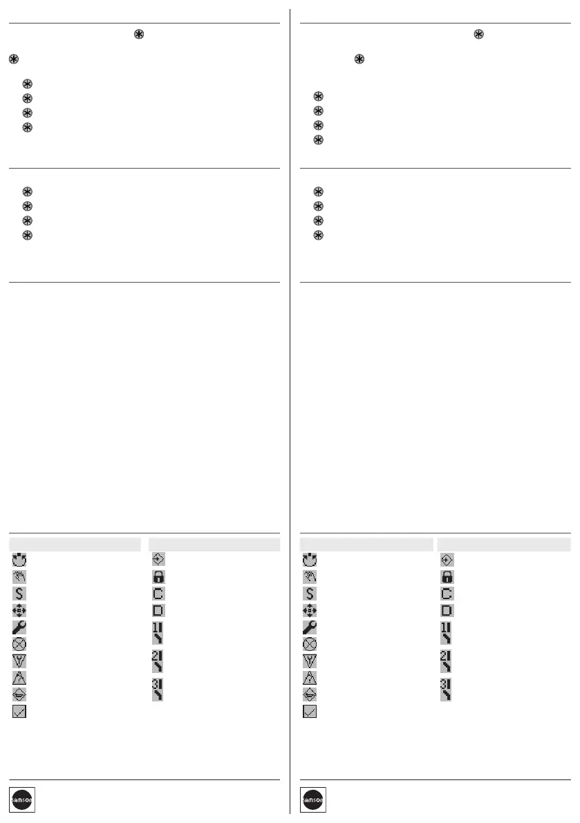
Icon Meaning
Automatic mode
Manual mode
Fail-safe position
Open-loop control mode
Function mode
Failure
Function check
Out of specication
Maintenance demanded
OK
Icon Meaning
Conguration enabled
Write protection
Option module in slot C
Option module in slot D
Binary contact 1 active
Binary contact 2 active
Binary contact 3 active
5 Initialization
WARNING! Risk of crushing! During initialization, the valve moves
through its entire travel range/angle of rotation.
Note: Before initialization, mount the positioner on the control valve.
Connect the air supply and input signal.
For normal operation, simply start initialization by pressing the INIT
key (mode: MAX, closed position: ATO).
Î Use a thin, pointed object to press the initialization key: the posi-
tioner adapts itself automatically to the maximum travel range/
angle of rotation of the control valve.
Note: After changing the mounting situation, reset the positioner
before initialization (refer to mounting and operating instructions).
Tip: We recommend setting the software restriction in the positioner
for actuators with diaphragm areas ≤240cm² to 50% (start-up menu
7.21/7. 22).
Refer to the mounting and operating instructions for other initializa-
tion modes and details.
4 Start-up
During the rst start-up, the wizard starts automatically:
1.
to determine the reading direction of the display.
2. (2x) to conrm.
3. to select language.
4. (3x) to conrm. The positioner changes to the start screen.
5. Initialize the positioner (see section 5).
6 Display icons and their meaning
Ausgabe Mai 2018 Kurzanleitung KA 8493
3 Bedienung
Durch Drehen () des Dreh-/Druckknopfes werden Menüpunkte,
Parameter und Werte ausgewählt. Drücken ( ) des Knopfes bestätigt
die Auswahl. für 2s, um eine Ebene zurück zu wechseln.
Um Parameter zu ändern, muss vorher die Kongurationsfreigabe
aktiviert werden:
1.
, um ins Hauptmenü zu wechseln.
2. , bis „Benutzerebene” erscheint.
3. und bis „Vor Ort: Schreiben” erscheint.
4. , um zu bestätigen.
Einzelheiten vgl. zugehörige Einbau- und Bedienungsanleitung:
uEB8493 für TROVIS3793
uEB8493S für TROVISSAFE3793
Symbol Bedeutung
Automatikbetrieb
Handbetrieb
Sicherheitsstellung
Steuerungsmodus
Funktionsmodus
Ausfall
Funktionskontrolle
außerhalb d. Spezikation
Wartungsanforderung
OK
Symbol Bedeutung
Kongurationsfreigabe
Schreibschutz
Optionsmodul in Steckpl. C
Optionsmodul in Steckpl. D
Binärkontakt 1 aktiv
Binärkontakt 2 aktiv
Binärkontakt 3 aktiv
4 Inbetriebnahme
Bei Erstinbetriebnahme startet das Gerät mit dem Assistenten:
1.
, um Leserichtung des Displays festzulegen.
2. (2x), um zu bestätigen.
3. , um Menüsprache zu wählen.
4. (3x), um zu bestätigen, Startbildschirm erscheint.
5. Stellungsregler initialisieren (vgl. Kapitel 5).
5 Initialisierung
WARNUNG! Quetschgefahr! Während der Initialisierung durchfährt
das Ventil den gesamten Hub-/Winkelbereich.
Info: Vor der Initialisierung den Stellungsregler montieren, pneuma-
tische Hilfsenergie aufschalten und Eingangssignal anschließen.
Für den Normalbetrieb reicht die Schnellinitialisierung über den Ini-
tialisierungstaster aus (Modus: MAX, Schließstellung: ATO).
Î Initialisierungstaster mit einem dünnen, spitzen Gegenstand be-
tätigen: Der Stellungsregler adaptiert sich anschließend vollauto-
matisch auf den maximalen Hub-/Drehwinkelbereich des Stell-
ventils.
Info:
Nach Änderung der Einbausituation, den Stellungsregler vor
der Initialisierung resetten (vgl. EB).
Tipp: SAMSON empehlt, bei Antrieben mit einer Membranäche
≤240cm² die Softwaredrossel des Stellungsreglers auf 50% einzu-
stellen (Inbetriebnahme-Menü 7.21/7.22).
Weitere Initialisierungsarten sowie Einzelheiten vgl. EB.
6 Displaysymbole und ihre Bedeutung
 Loading...