EasyManua.ls Logo

Samson 3730 Series User Manual

Samson 3730 Series
216 pages
To Next Page IconTo Next Page
Page #1 background imageLoading...
Page #1 background image
Translation of original instructions
EB 8384-3 EN
Firmware version 1.61
Edition April 2022
Series3730
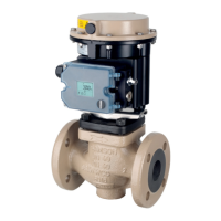
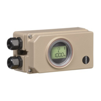
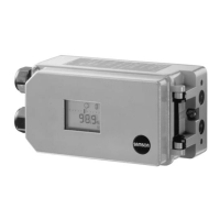
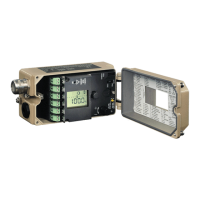
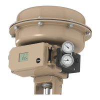
Type3730-3 Electropneumatic Positioner
Communication: HART
®
Old design
New design

Table of Contents

Other manuals for Samson 3730 Series

Questions and Answers:

Samson 3730 Series Specifications

General IconGeneral
BrandSamson
Model3730 Series
CategoryValve Positioners
LanguageEnglish

Summary

Definition of signal words

Safety instructions and measures

Notes on possible severe personal injury

Details risks associated with explosive atmospheres and potential fatal injuries.

Notes on possible personal injury

Highlights crush hazards from moving valve parts and electrical connection risks.

Notes on possible property damage

Covers risks of damage due to incorrect mounting, lever installation, and electrical signals.

Special instructions concerning explosion protection

Provides specific guidance for operation in explosive atmospheres (Zone 21, 22, and equipment for Zone 2).

Markings on the device

Nameplate

Details information displayed on the device nameplate for both explosion-protected and non-protected versions.

Article code

Explains the coding system used to specify positioner type, explosion protection, and options.

Firmware versions

Lists revisions of firmware, detailing new features and changes introduced in each version.

Design and principle of operation

Mounting versions

Outlines the different types of attachment for the positioner to various actuators.

Additional equipment

Describes optional components like solenoid valves and position transmitters and their functions.

Communication

Explains the communication interface, specifically HART® protocol, for data transmission.

Configuration using the TROVIS-VIEW software

Details how to configure the positioner using SAMSON's TROVIS-VIEW software.

Technical data

Provides detailed specifications, including valve travel, set point, supply air, and environmental limits.

Dimensions in mm

Shows dimensional drawings for various attachment types and mounting configurations.

Shipment and on-site transport

Accepting the delivered goods

Guides on checking the scope of delivery and identifying transportation damage upon receipt.

Removing the packaging from the positioner

Provides instructions on safely removing packaging and protective caps before installation.

Transporting the positioner

Outlines precautions and instructions for proper transportation to prevent damage.

Storing the positioner

Details recommended storage practices to avoid device damage and maintain integrity.

Installation

Installation conditions

Specifies requirements for work position, mounting orientation, and ensuring accessibility.

Preparation for installation

Lists pre-installation checks and steps, including material readiness and pneumatic connections.

Adjusting the lever and pin position

Explains how to set the lever and follower pin for correct actuator adaptation and travel.

Exchanging the lever

Describes the procedure for replacing the lever, differentiating between versions with and without a sliding clutch.

Positioner attachment

Provides detailed instructions for attaching the positioner to various actuator types using specific mounting kits.

Attachment of external position sensor

Explains how to mount an external position sensor to the positioner for position feedback.

Operation

Adapting the display direction

Allows rotating the display by 180° for optimal readability based on mounting orientation.

Changing the operating mode

Explains how to switch between automatic, manual, and fail-safe modes.

Performing zero calibration

Guides on recalibrating the zero point when inconsistencies are detected in the valve's closed position.

Resetting the positioner

Describes how to reset all parameters and diagnosis data to factory defaults.

Start-up and configuration

Determining the fail-safe position

Guides on setting the fail-safe position based on valve type and actuator direction.

Adjusting the volume restriction Q

Explains how to adapt air output capacity to actuator size using volume restriction settings.

Limiting the signal pressure

Details how to limit signal pressure to prevent actuator force damage to the valve.

Checking the operating range of the positioner

Outlines steps to verify mechanical attachment and proper function by moving the valve through its range.

Initializing the positioner

Covers the process of adapting the positioner to actuator friction and signal pressure requirements.

Setting other parameters

Refers to Annex A for codes and meanings of other configurable parameters.

Adjusting inductive limit switch

Explains how to adjust the tag and proximity switch for the inductive limit switch option.

Malfunctions

Troubleshooting

Provides guidance on identifying and resolving common errors, including fault alarm outputs.

Emergency action

Describes actions to take in case of i/p converter or solenoid valve failure, or supply air failure.

Servicing

Cleaning the cover window

Instructions for safely cleaning the positioner's cover window.

Cleaning the filters

Details how to remove and clean internal filters in pneumatic connections.

Maintenance of the supply air pressure reducing stations

Refers to observing maintenance instructions for upstream supply air components.

Firmware updates

Outlines the process for performing firmware updates on the positioner, both on and off-site.

Periodic inspection and testing of the positioner

Recommends periodic checks and tests based on Table 10-1 for ensuring proper function.

Decommissioning

Removal

Repairs

Servicing explosion-protected devices

Specifies requirements for servicing devices in potentially explosive atmospheres, including inspections and part replacements.

Returning devices to SAMSON

Outlines the process for returning defective devices to SAMSON for repair.

Disposal

Certificates

Annex A (configuration instructions)

Parameters and functions

Details various configurable parameters, their readings, and descriptions for positioner setup.

Error codes

Lists initialization errors, their causes, status classifications, and recommended actions for troubleshooting.

Valve characteristic selection

Illustrates different valve characteristics (Linear, Equal Percentage) in graphical form.

Annex B

Accessories

Lists general accessories, mounting parts, and pressure gauge kits with their order numbers.

After-sales service

Provides contact information and required details for service, repair, and support.

Related product manuals