Do you have a question about the Samson 3730-3 and is the answer not in the manual?
Indicates that the following content is a translation of the original instructions.
Identifies the specific model and communication protocol of the device.
Details the intended application and operational scope of the positioner.
Outlines applications and activities that are not in line with the device's intended use.
Specifies the required training and experience for personnel handling the device.
Information regarding necessary personal protective equipment for handling the positioner.
Advises against unauthorized changes to the product.
Describes the device's behavior during air supply or electric signal failure.
Highlights potential hazards from process medium, signal pressure, or moving parts.
Details safety requirements for operation in explosive dust atmospheres.
Guidelines for servicing devices used in potentially explosive atmospheres.
Instructions for maintenance and calibration procedures.
Defines the operator's duties regarding safety regulations and personnel instruction.
Outlines the responsibilities of operating personnel regarding safety instructions and regulations.
Lists applicable standards and regulations the device complies with.
Identifies additional documents relevant to the installation and operation.
Details risks of severe injury due to explosive atmospheres and installation procedures.
Warns about risks of injury from moving valve parts during operation.
Highlights risks of damage to the positioner from incorrect mounting or startup.
Description of the information found on the device's nameplate.
Explains the structure and meaning of the product's article code.
Details the history and changes in firmware versions.
Illustrates the functional components and connections of the positioner.
Describes the different types of attachment methods for the positioner.
Details optional accessories and their functions.
Explains the function and detection capabilities of the leakage sensor.
Describes the functionality and configuration of the binary input option.
Information on communication protocols and interfaces supported by the positioner.
Guide on configuring the positioner using the dedicated software.
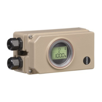
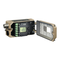
Provides an overview of the device's physical layout and controls.
Lists available accessories for general use and specific attachments.
Provides data on actuator sizes, travel ranges, and lever/pin positions.
Comprehensive technical specifications of the positioner.
Illustrates the physical dimensions of the positioner in various mounting configurations.
Specifies fixing levels and dimensions for rotary actuators.
Instructions for safely unpacking the positioner and its components.
Guidelines for protecting the positioner during transportation.
Recommendations for proper storage to prevent damage.
Details on the correct and incorrect mounting orientations for the positioner.
Instructions for setting the lever and follower pin for travel adjustment.
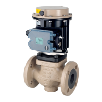
Specific mounting instructions for direct attachment to actuators.
Procedure for mounting using NAMUR rib or rod-type yokes.
Instructions for mounting the positioner using VDI/VDE 3847-1 standard.
Steps for attaching the positioner to rotary actuators via VDI/VDE 3847-2.
Mounting procedures for single-acting actuators.
Mounting procedures when using a reversing amplifier for double-acting actuators.
Information on using an intermediate plate for specific actuator interfaces.
Instructions for mounting a solenoid valve as an accessory.
Procedure for attaching the positioner to a Type 3510 Micro-flow Valve.
General instructions for mounting the positioner to rotary actuators.
Specific mounting instructions for heavy-duty rotary actuator versions.
Details on mounting a reversing amplifier for double-acting actuators.
Specific mounting instructions for alternative reversing amplifier models.
Instructions for attaching pressure gauges to the pneumatic connections.
Procedures for mounting an external position sensor.
Steps for mounting the position sensor directly onto the actuator.
Instructions for mounting the sensor using IEC 60534-6 compliant attachment.
Procedure for mounting the position sensor on a Type 3510 Micro-flow Valve.
Steps for mounting the position sensor onto rotary actuators.
Instructions for installing the leakage sensor.
Guide for adding an inductive limit switch to the positioner.
Specific mounting requirements for positioners with stainless steel housings.
Details on the air purging function for corrosion protection.
Information on connecting pneumatic lines to the positioner.
Step-by-step instructions for connecting the main air supply.
Recommendations for monitoring supply and signal pressure.
Defines the required supply air pressure based on actuator type and fail-safe action.
Specifies the output signal pressure limits and software limitations.
Guidance on making safe and compliant electrical connections.
Instructions for connecting the mA signal and electrical power.
Information on connecting switching amplifiers for limit switch operation.
Steps to establish communication via HART® protocol or serial interface.
Description of the rotary pushbutton for device operation.
Explanation of the slide switch for controlling valve direction.
How to adjust air output capacity based on actuator size.
Explanation of icons and symbols displayed on the positioner.
Details on automatic, manual, and fail-safe operating modes.
Interpreting the bar graph for set point deviation or lever position.
Understanding status messages indicating errors or maintenance needs.
Process for enabling configuration of device parameters.
Information on connecting and communicating via the serial interface.
Details on establishing and managing HART® communication.
Procedure for enabling or disabling write access for HART® communication.
How to lock or unlock on-site operation via HART® communication.
Explanation of dynamic HART® variables and their assignment.
General instructions for operating the positioner after installation.
Steps to define and set the valve's fail-safe position.
Procedure for adjusting volume restriction for optimal actuator performance.
How to adjust the display orientation for readability.
Instructions for limiting signal pressure to prevent valve damage.
Procedure to verify the mechanical attachment and proper functioning.
Detailed steps for initializing the positioner for optimal performance.
Initialization mode for simple setup with clearly defined mechanical end positions.
Initialization mode for accurate valve travel setup using calibrated sensor.
Initialization mode for manually defining the operating range.
Method for replacing a positioner with minimal plant disruption.
Procedure to recalibrate the zero point for valve inconsistencies.
Guide on adjusting the inductive limit switch for position detection.
Function to reset all parameters to factory default settings.
Process for enabling and configuring various device parameters.
Details on automatic and manual operating modes.
Procedure to move the valve to its determined fail-safe position.
Information on filters in pneumatic connections that can be removed and cleaned.
Highlights the need to observe maintenance instructions for pressure reducing stations.
Instructions for updating the positioner's firmware.
Procedure for updating firmware when the device is outside a hazardous area.
Conditions and permits required for performing updates on-site.
Steps to follow when returning defective positioners for repair.
Indicates a functional fault preventing control task execution.
Signals a need for maintenance due to wear or demand.
Indicates a short-term maintenance need for continued operation.
Highlights operation outside specified environmental conditions.
Procedure to view and confirm error messages displayed on the positioner.
Describes actions to take in case of valve or actuator failure.
Steps to safely decommission the positioner before removal.
Instructions for disconnecting and removing the positioner from the valve.
Guidelines for the proper disposal of the positioner and its components.
Contact information for support, service, and repair inquiries.
Information on obtaining explosion-protection certificates and declarations of conformity.
Reference for all available codes, parameters, readings, and their descriptions.
List of error codes, their causes, status classifications, and recommended actions.
Illustrates selectable valve characteristics for positioner configuration.
| Brand | Samson |
|---|---|
| Model | 3730-3 |
| Category | Valve Positioners |
| Language | English |

