EasyManua.ls Logo

Samson TROVIS 3730-1 User Manual

Samson TROVIS 3730-1
108 pages
To Next Page IconTo Next Page
Page #1 background imageLoading...
Page #1 background image
Translation of original instructions
EB 8484-1 EN
Firmware version 3.00.04
Edition January 2019
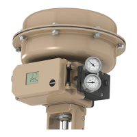
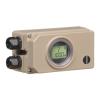
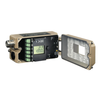
TROVIS3730-1 Electropneumatic Positioner

Table of Contents

Other manuals for Samson TROVIS 3730-1

Questions and Answers:

Samson TROVIS 3730-1 Specifications

General IconGeneral
TypeElectropneumatic positioner
Input signal4 to 20 mA
Output signalPneumatic
Protection classIP 66
CommunicationHART
Signal range4 to 20 mA
Ambient temperature range-40 to +80 °C (-40 to +176 °F)
Enclosure ratingIP 66
Housing materialAluminum

Summary

Safety Instructions and Measures

Intended use

Defines the primary application and operational constraints of the positioner.

Qualifications of operating personnel

Specifies the necessary training and expertise for personnel handling the device.

Warning against residual hazards

Advises on potential hazards from process medium, pressure, or moving parts.

Servicing explosion-protected devices

Guidelines for maintenance and inspection of explosion-protected versions.

Notes on possible severe personal injury

Warns of fatal injury risks due to explosive atmospheres and installation errors.

Notes on possible personal injury

Warns of injury risk from moving valve parts during initialization or operation.

Design and principle of operation

3.2 Configuration using the TROVIS-VIEW software

Explains how to use the software for device configuration and parameter monitoring.

3.7 Technical data

Lists specifications for travel, set point, supply air, and performance.

Measures for preparation

Mounting and start-up

5.1 Mounting position

Specifies correct placement of the positioner on the valve to avoid damage.

5.2 Lever and pin position

Explains how to set the lever and pin for actuator adaptation and travel adjustment.

5.3 Direct attachment

Details the process for direct mounting to specific actuator types.

5.3.1 Type 3277-5 Actuator

Provides specific instructions for direct attachment to the Type 3277-5 actuator.

5.3.2 Type 3277 Actuator

Offers specific instructions for direct mounting to the Type 3277 actuator.

5.4 Attachment according to IEC 60534-6

Outlines the procedure for mounting via NAMUR rib or rod-type yokes.

5.5 Attachment according to VDI/VDE 3847-1

Describes attachment methods for quick replacement while the process is running.

5.6 Attachment according to VDI/VDE 3847-2

Explains mounting for specific rotary actuators with NAMUR interface.

5.6.1 Version for single-acting actuator

Details the mounting process for single-acting actuators using specific adapter kits.

5.6.2 Version for double-acting actuator

Provides mounting instructions for double-acting actuators, including reversing amplifiers.

5.7 Attachment to Type 3510 Micro-flow Valve

Details the process for attaching the positioner to a Micro-flow Valve using a bracket.

5.8 Attachment to rotary actuators

Describes mounting the positioner to rotary actuators using brackets.

5.8.1 Heavy-duty version

Specifies mounting procedures for the heavy-duty version of rotary actuator attachments.

5.13 Connecting the supply air

Outlines the sequence for connecting supply air and other utilities.

5.14 Electrical connections

Covers safety precautions and general guidelines for electrical connections.

Optional additional functions

Operation

Operating the positioner

8.3 Entering the fail-safe position

Guides on defining the valve's fail-safe state based on type and action.

8.4 Initialization

Describes the process of adapting the positioner to actuator friction and signal pressure.

8.5.6 Performing zero calibration

Provides instructions for recalibrating the zero point to correct valve closing inconsistencies.

Maintenance

Malfunctions

10.2 Error codes

Lists error codes, their descriptions, and classification based on operational impact.

Decommissioning and removal

Related product manuals