EB 8384-3 EN 5-45
Installation
resistance of the supply leads into account,
the voltage at the position transmitter termi-
nalscanbebetween12and30VDC.
Refer to Fig.5-31 or to the label on the ter-
minal block.
Malfunction due to the current falling below
minimum current.
Î Do not allow the set point to fall below
3.8mA.
In positioners for attachment according to
VDI/VDE3847-1, the terminal designation
of the limit switches 41/42 and 51/52 as
well as the OPEN and CLOSED wording can
be changed by turning the terminal label
which is printed on both sides.
Connecting the electrical power
Before performing the electrical connection,
make sure the following conditions are met:
− The positioner is properly mounted onto
the control valve.
− The air supply is properly connected.
If this is the case:
Î Connect the electrical power (mA signal)
as shown in Fig.5-31.
NOTICE
Note
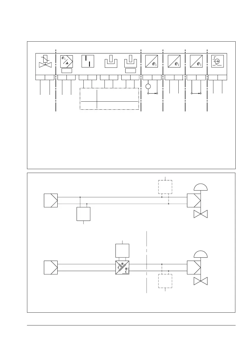
G
+81 -82 +11 -12
+83
-84 +51
-52
A2A3 A1
+41 -42
+31 -32
A
+31 -32
+31 -32
+31 -32
G G
Optional Optional Optional
24VDC
Solenoid
valve
(optional)
mA
control
signal
A3
Fault
alarm
A2
Software
A1
Software
optionally
inductive
Limit switches
Analog
input x
Leakage
sensor
Position
transmitter
with two-
wire
transmitter
supply unit
Binary
input
Non ex
Binary input
1)
of a PLC or
switchingamplier
2)
Ex
Switchingamplier
2)
Optional Optional
1)
Binaryinputacc.toIEC61131-2(Pmax=400mW)
2)
SwitchingamplieraccordingtoEN60947-5-6
Fig.5-31: Electrical connections
Connection in safe area
Connection in hazardous area
Controller/
control station
Controller/controlstation
Handheld communicator or
second FSK modem
4to20mA
Safe range Hazardous area
Handheld communicator or second
FSK modem (explosion-protected)
Explosion-protected
isolationamplier
Fig.5-32: Connection with FSK modem

 Loading...


