EB 8384-3 EN 3-1
Design and principle of operation
3 Design and principle of oper-
ation
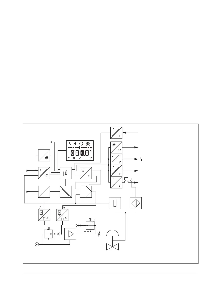
Î See Fig.3-1
The electropneumatic positioner is mounted
on pneumatic control valves and used to as-
signthevalveposition(controlledvariablex)
tothecontrolsignal(setpointw).Theelectric
signal from a controlling system is compared
to the travel or the rotational angle of the
control valve and a signal pressure (output
variable y) is produced for the actuator.
The positioner consists of a travel sensor sys-
tem (2) proportional to resistance, an analog
i/pconverterwithadownstreamairbooster
(7) and the electronics with microcontroller
(5).
Thepositioneristtedwiththreebinarycon-
tacts as standard: A fault alarm output indi-
cates a fault to the control room and two con-
gurablesoftwarelimitswitchesareusedto
indicate the end positions of the valve.
The valve position is transmitted as a either
an angle of rotation or travel to the pick-up
1 Control valve
2 Travel sensor
3 PD controller
4 A/Dconverter
5 Microcontroller
6 i/pconverter
7 Air booster
8 Pressure regulator
9 Flow regulator
10 Volumerestriction
11* Inductive limit switch
12* Solenoid valve
13* Analog position transmitter
14 Software limit switch, alarm
1/2
15 Fault alarm output, alarm 3
16 Display
17* Actuation of solenoid valve
18* Galvanic isolation
19 D/Aconverter
20 Communication interface
21 HART
®
connection
22 Binary input BE*
* Option
w
x
Q
%
S
mm
GG
PD
Serial
Interface
16
13
22
15
A2
A3
A1
11
2
4
21
FSK
20
19
5
3
12
6
7
8
10
1
14
14
w
x
y
9
17
18
Fig.3-1: Block diagram

 Loading...


