Do you have a question about the Samsung AQV12VBC and is the answer not in the manual?
| Brand | Samsung |
|---|---|
| Model | AQV12VBC |
| Category | Air Conditioner |
| Language | English |
Guidelines for safe installation of the air conditioner, emphasizing professional installation.
Safety precautions regarding power supply, circuit breakers, and wiring.
Safety measures to follow while operating the air conditioner, including maintenance and child safety.
Procedures for safely disposing of the air conditioner unit and its components.
Miscellaneous safety notes regarding storage, supervision, and measurement standards.
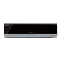
Highlights key features like High Energy Efficiency, Luxury Half Mirror Design, and special modes.
Detailed technical specifications including capacity, performance, power, and size.
Comparison of key specifications between AQV09VBC and AQV12VBC models.
List of accessories included with the indoor and outdoor units.
Procedure for entering and operating the air conditioner's test mode for checks.
Explains indoor unit error codes displayed and their corresponding check methods.
Explains outdoor unit LED error displays and their corresponding check methods.
Step-by-step guide for setting up product options using the remote control.
Lists the essential tools required for disassembly and reassembly procedures.
Detailed steps for disassembling the indoor unit, including panel and filter removal.
Detailed steps for disassembling the outdoor unit, including cover and component removal.
Exploded view and parts list for the indoor unit, identifying each component.
Exploded view and parts list for the outdoor unit, identifying each component.
List of electrical components for the main PCB, including location, code, and specification.
List of electrical components for the sub PCB, including location, code, and specification.
List of electrical components for the outdoor PCB, including location, code, and specification.
List of electrical components for the EMI PCB, including location, code, and specification.
Wiring diagram illustrating the electrical connections within the indoor unit.
Wiring diagram illustrating the electrical connections within the outdoor unit.
Schematic diagram of the indoor unit's electronic circuitry and component layout.
Schematic diagram of the outdoor unit's electronic circuitry and component layout.
Detailed descriptions of PCB circuits for the indoor unit's main components.
Diagram illustrating the refrigerating cycle of the air conditioner, showing component flow.
Visual diagram of the indoor unit's PCB, showing component locations and connections.
Visual diagram of the outdoor unit's PCB, showing component locations and connections.
Identifies and labels the parts of the indoor unit with visual aids.
Identifies and labels the parts of the outdoor unit with visual aids.
Explains the buttons and display functions of the wireless remote control.
Describes the fundamental operational modes of the air conditioner.
Explains advanced or special functions like good'sleep, Silence, and MPI modes.
Initial checks and common issues before diagnosing faults, including voltage and wiring.
Diagnosing faults based on observed symptoms and system behavior.
Methods for inspecting PCBs, including pre-inspection notices and detailed procedures.
Methods for inspecting key components like sensors and motors using a tester.
Troubleshooting steps for units that show no power or are completely dead.
Troubleshooting steps for errors related to the outdoor unit's power supply.
Troubleshooting guide for the up/down louver motor not operating correctly.
Troubleshooting steps for errors related to the outdoor unit fan operation.
Troubleshooting steps for errors indicating a total current trip.
Troubleshooting for incorrect heating/cooling mode operation.
Troubleshooting steps for errors related to the outdoor temperature sensor.
Troubleshooting steps for errors related to the discharge temperature sensor.
Troubleshooting steps for errors related to the coil temperature sensor.
Troubleshooting steps for errors related to the fan operation.
Troubleshooting steps for errors related to the DC-Link voltage sensor.
Troubleshooting steps for errors indicating over current conditions.
Troubleshooting steps for communication errors between indoor and outdoor units.
Troubleshooting steps for errors related to the compressor failing to start.
Troubleshooting steps for errors indicating the compressor is locked.
Troubleshooting steps for DC Link over or low voltage errors.
Troubleshooting for issues where the remote control is not received by the unit.
Addresses other miscellaneous troubleshooting issues like AC Line Zero Cross and Capacity miss match.
Block diagram illustrating the indoor unit's control system and component interactions.
Block diagram illustrating the outdoor unit's control system and component interactions.
Guide for interpreting model names and their components based on code structure.
Chart showing refrigerant pressure distribution based on indoor and outdoor temperatures.
Conversion table for various units of pressure and capacity measurements.
Frequently asked questions and answers for common non-trouble issues and user queries.
Guidelines and procedures for installing the air conditioner unit correctly.
Instructions for cleaning the air conditioner and changing its filters regularly.
Diagrams illustrating the installation process, including air-purge and pump-down procedures.
Preparation steps and considerations before installing the unit, including surroundings and symmetry.
Step-by-step guide for the installation process: location, wall drilling, piping, and testing.
Guide for cleaning the indoor unit and its air filter using vacuum or brush.
Instructions for cleaning the anti-allergy filter, emphasizing washing and drying methods.
Instructions for replacing the deodorizing filter, which absorbs odors efficiently.
Procedure for purging air from the refrigerant system using a vacuum pump.
Procedure for pumping down refrigerant when replacing parts or relocating the unit.