3
SAMSUNG ELECTRONICS
8. PCB Diagram 79
8-1 Indoor Main PCB-DB92-04839A 79
8-2 Outdoor PCB-DB92-04837A 80
8-3 Outdoor PCB-DB92-04838A 82
8-4 DISPLAY PCB-DB92-04833B 83
8-5 Wire connecting the indoor unit terminal blocksl 84
9. Operating Instructions 85
9-1 Name of Each Part 85
9-2 Wireless Remote Control-Buttons and Display 86
10. Troubleshooting 87
10-1 Items to be checked First
87
10-2 Communication Error 88
11. Block Diagram 106
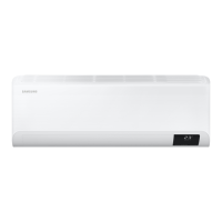
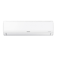
11-1 Indoor unit 106
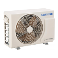
11-2 Outdoor unit 107
12. Reference Sheet 110
12-1 Low Refrigerant Pressure Distribution 110
12-2 Pressure & Capacity mark 110
12-3 Q & A for Non-trouble 111
12-4 Cleaning /Filter Change 114
12-5 Installation 118
12-6 Installation Diagram of Indoor Unit and Outdoor Unit 119
12-7 Reference sheet 122

 Loading...


