105
SAMSUNG ELECTRONICS
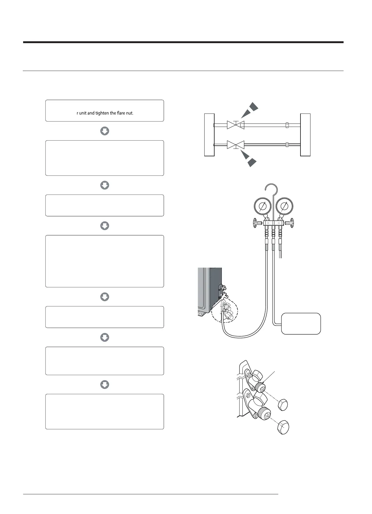
11-6 Installation Diagram of Indoor Unit and Outdoor Unit
11-6-1 Air-Purge Procedure
1) Connect each assembly pipe to the appropriate valve on
the outdoo
2) Connect the charging hose of low pressure side of
manifold gauge to the packed valve having a
service port (3/8" Packed valve) as shown at the
gure.
Indoor unit
Outdoor unit
A C
Gas pipe side
D
Liquid pipe side
B
6) Mount the valve stem nuts to the 2 way and
3 way valve. And mount the service port cap to
3 way valve.
3) Open the valve of the low pressure side of manifold
gauge counter-clockwise.
4) Purge the air from the system using vacuum pump for
about 30 minutes.
- After that, please recheck that pressure is stabilized.
- Close the valve of the low pressure side of manifold
gauge clockwise.
- Remove the hose of the low pressure side
of manifold gauge.
5) Set valve cork of both liqui
d side and gas side of packed
valve to the open position.
Vacuum Pump
7) Check for gas leakage.
- At this time, especially check for gas
leakage from the 3 way valve's stem nuts,
and from the service port cap.
Valve stem
Stem cap
A
(gas)
B
(liquid)