Samsung DCS Part 2
Installation March 2001
3
Part 2. Installing Basic KSU and Expansion
Cabinets
2.1 Unpacking and Inspection
After unpacking the KSU and expansion cabinets, inspect for signs of physical damage. If any dam-
age is detected, do not attempt to install. Contact your dealer for advice.
Check to see that the KSU carton includes the following items:
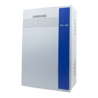
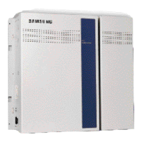
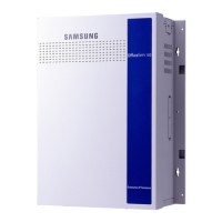
• Key service unit
• System Administration Manual.
• Wall mount bracket and four (4) screws: two long with washers and two short
• Power cord
• Ferrite core for power cord (for electrical “noise” suppression)
The power supply unit is supplied in a separate box.
Check to see that each expansion cabinet carton includes the following items:
•
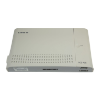
Expansion cabinet
•
Power extension cable
•
Wall mount bracket and four (4) screws: two long with washers and two short
•
HDLC cable for connecting to main KSU
The power supply unit is supplied in a separate box.
All other system cards including the expansion cards are supplied separately.
2.2 Single Cabinet Installation
The KSU must be wall-mounted using the bracket supplied.
1. Mount the KSU on a plywood backboard at least 15 mm thick.
2. Attach the mounting bracket to the backboard with the two shorter screws supplied (Figure 2–1).
3. Hang the KSU on the mounting bracket and secure it to the backboard with the remaining two
screws and washers (Figure 2–2).
4. Remove the power supply from its unit carton and install in the slot labelled PSU.
5. Set the battery switch. The switch is located at the bottom of the ROM card slot in the base of the
KSU and is set OFF by default. Set the switch to ON. (The switch is shown in Figure 2-5.)