Do you have a question about the Samsung DCS-408i and is the answer not in the manual?
Details on publication rights, revisions, and changes to design or components.
Limits Samsung Telecoms' responsibility for errors in installation, programming, or operation.
Declaration of conformity to EU directives by the manufacturer and EU representative.
Describes the system's purpose for voice communication and potential CTI functions.
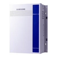
Highlights key features like slim design, Plug & Play, call list display, and port capacity.
Provides general technical details including CPU, memory, switch structure, and SIO port.
Details physical dimensions, weight, and system capacity for trunks and stations.
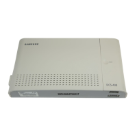
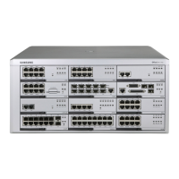
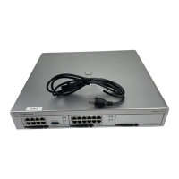
Illustrates front and rear views, detailing system ports like BRI, SLI, DLI, and MISC.
Provides essential safety guidelines for installation, operation, and cleaning to prevent hazards.
Specifies environmental conditions and precautions for installation, including static electricity.
Outlines cable requirements, maximum lengths, and emphasizes using a dedicated AC power supply.
Instructions for unpacking the system unit and verifying included items.
Step-by-step guide with diagrams for removing the unit's side and front covers.
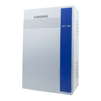
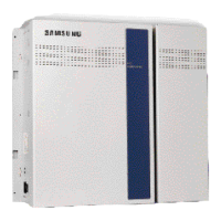
Diagrams showing internal components of DCS-408 and DCS-408i systems.
Instructions on how to reattach the front and side covers after internal access.
Explains the necessity of grounding and details the optional external ground connection process.
Provides instructions for securely mounting the system unit onto a wall using provided hardware.
Guides users through initial power-on checks, including LED status verification.
Troubleshooting steps for specific red LED light conditions during initial operation.
Details required battery specifications and considerations for selecting an appropriate battery.
Provides a critical warning and step-by-step instructions for connecting the battery backup.
Illustrates modular jack locations and describes the types of cables required for connections.
Lists specific cable types (RJ-45, RJ-11) and pin configurations for various ports.
Instructions on using supplied cable ties for organizing connected cables.
Detailed pin number and function mapping for BRI, CO, SLI, DLI, and MISC ports.
Explains how to connect analogue trunks (RJ-11) and digital trunks (RJ-45).
Details the selection and installation of MPD/PRS hybrid chips for trunk interface lines.
Provides safety warnings and general guidance for connecting telephones to the system.
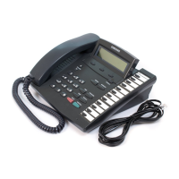
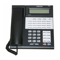
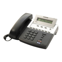
Instructions for connecting digital and analogue keysets to DLI and SLI ports respectively.
Explains the function and setting of the memory backup switch for retaining programmed data.
Describes how to select internal or external music sources using a jumper.
Details the numerical assignment for trunk and station ports, including BRI2 substitution.
Covers programming keys for various Samsung digital keysets and refers to programming manuals.
Guides on replacing system ROM chips for upgrades or bug fixes.
Details how to connect external music sources like CD players or radios to the MISC port.
Explains connecting paging equipment to the MISC port and assigning page zone numbers.
Describes connecting a common bell to the MISC port's dry contact pins and assigning it to groups.
Instructions for connecting a serial printer to the SIO port for SMDR output.
Details connecting a PC or modem to the SIO port for system programming and remote access.
Explains setting SIO port type to 'PCMMC' in MMC 804 for PC communication.
Describes connecting the CTM to a PC and digital keyset for CTI functionality.
Details connecting voice mail/auto attendant to the SLI4 port for call signaling.
Instructions for connecting a Doorphone Interface Module (DPIM) to doorphones and lock releases.
Provides specifications for AC input, power consumption, and physical dimensions.
Details operating temperature, humidity, storage, and line cable specifications.
Lists specifications for external music source input and external page impedance.
Lists common issues like power failure, no display, and non-operational keysets with suggested actions.
Defines technical terms from AUXILIARY RING to MODULAR JACK.
Defines technical terms from PORT (CIRCUIT) to VOICE MAIL (VMS).
| Extensions | 8 |
|---|---|
| System Type | Hybrid |
| Maximum Extensions | 8 |
| Maximum CO Lines | 4 |
| Lines | 4 |
| Display | No |
| Power Supply | AC 100-240V, 50/60Hz |