Samsung
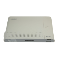
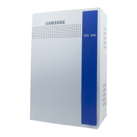
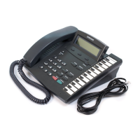
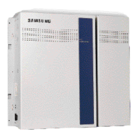
DCS-408 & 408i Keyphone System Installation Manual
– 29 –
Voice Mail/
Auto
Attendant
The pin connections from the CTM to the PC are as follows.
CTM PC
COM1 COM2
9-PIN 25-PIN
TXD(2) ----------------------------------------------- RXD(2) RXD(3)
RXD(3) ----------------------------------------------- TXD(3) TXD(2)
GND(5) ----------------------------------------------- GND(5) GND(7)
Voice Mail/Auto Attendant
If you connect a voice mail system or automated attendant to a corresponding circuit of the
keyphone system, the common bell can receive a call signal as if it is one of the stations.
Set a port in MMC 207, Assign VM/AA Port, and set the necessary parameters in MMC 726,
VM/AA Options. You should connect voice mail/auto attendant to the SLI4 port only.
The following table shows the arrangement of pins for the modular jack when connecting
voice mail/auto attendant.
SLI4 Port
(RJ-45 [4-pin] Modular Jack)
Pin number Features
1, 4 Not Used
2, 3 SLI4
NOTE: Always connect the voice mail/auto attendant to the SLI4 port. Connecting the voice
mail/auto attendant to an SLI1–SLI3 port may cause critical errors.
Doorphone and Door Lock Release
Connect a Doorphone Interface Module (DPIM) to a doorphone using a pair of #24 AWG or
#26 AWG cables. Then, connect the DPIM to a DLI port of your choice using a pair of #24
AWG or #26 AWG cables.
Refer to the section Installing Cables
in Chapter 2 for details of the connection between the
DPIM and the DLI port.
If you want to use the automatic door lock release, connect the LOCK port on the DPIM to
the door lock release.
NOTE: Use only a Samsung 4-line keyset doorphone for this feature, which you can purchase
separately.
The following table and diagram show the arrangement of pins for the modular jack when
connecting a doorphone and door lock release to the DPIM.

 Loading...
