Do you have a question about the Samsung DMS2 and is the answer not in the manual?
Crucial safety guidelines for installation and repair of the DMS2, emphasizing professional service and structural integrity.
Precautions regarding location, environment, and usage to prevent damage or malfunction of the DMS2.
Details on required IP addresses (public/private) and DHCP support for DMS2 network setup.
Guidelines for connecting LAN/communication cables and choosing between static/dynamic IP for internet access.
Essential safety instructions for installation, including using provided parts and adhering to regulations.
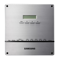
Overview of the external parts of the DMS2 unit, including display, buttons, and indicators.
Detailed explanation of the function and status indication of each LED on the DMS2 unit.
Detailed description of each terminal and connector on the DMS2 unit for various connections.
Description of the internal components and connections within the DMS2 unit.
Technical specifications detailing the physical size and measurements of the DMS2 unit.
Explains system connection configurations using centralized controllers and interface modules.
Important warnings about connecting controllers and modules to avoid communication issues and data retrieval problems.
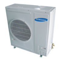
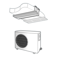
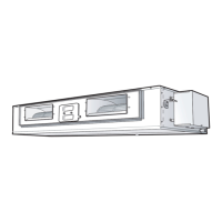
Lists compatible indoor/outdoor units, controllers, SIM, PIM, and interface modules for the DMS2.
Details compatible watt-hour meters, including connection types and third-party notes.
Specifies the maximum number of indoor units that can be connected to the DMS2.
Defines the maximum quantity of centralized controllers connectable to the DMS2.
States the maximum number of interface modules that can be connected to the DMS2.
Outlines the maximum connectable units for SIM/PIM and watt-hour meters.
Step-by-step guide for preparing and mounting the DMS2 unit using its installation plate.
Instructions for securing the DMS2 to the installation plate and using the wiring groove for rear wiring.
Steps for connecting power, communication cables, and LAN cable to the DMS2 for centralized controller setup.
Steps for connecting power, communication cables, and LAN cable to the DMS2 for interface module setup.
Steps for connecting power, communication cables, and LAN cable to the DMS2 for SIM unit setup.
Guide to configuring system settings via contact control patterns, including pattern descriptions and saving.
Details on actual DI port usage and reserved ports for future functions, emphasizing correct connection.
Detailed explanation of each control pattern (1-4), including input signals and operational effects.
Illustrates the DI input circuitry for Patterns 2, 3, and 4, showing connections for specific operations.
| Refrigerant | R410A |
|---|---|
| Cooling Capacity | 18000 BTU/h |
| HSPF Rating | 9 |
| Operating Temperature (Cooling) | 18°C to 46°C |
| Operating Temperature (Heating) | 5°F - 75°F |