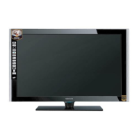
Do you have a question about the Samsung LE40F86BD and is the answer not in the manual?
Essential safety, servicing, and ESD precautions to prevent hazards and damage.
Precautions for technicians during servicing, including handling capacitors and insulation checks.
Techniques to reduce component damage caused by static electricity.
Safety guidelines for product installation, covering handling, ventilation, and electrical connections.
Details on TV features like connectivity and performance specifications.
Explanation of Motion Judder Cancellation technology and its board differences.
Comparison of technical specifications between the current models and older ones.
List of included accessories with their respective part codes and remarks.
Step-by-step guide for disassembling the LCD TV, detailing screw removal and component access.
Guides users through identifying and resolving common issues like no power, no video, and no sound.
Instructions for performing general alignment and factory mode adjustments.
Procedures for entering and utilizing factory mode for service adjustments and panel checks.
Illustrated exploded view of the LE40F86BD model, showing component layout and part references.
Detailed list of parts for the LE40F86BD model, including location, code, description, and quantity.
Illustrated exploded view of the LE46F86BD model, showing component layout and part references.
Detailed list of parts for the LE46F86BD model, including location, code, description, and quantity.
Illustrated exploded view of the LE52F96BD model, showing component layout and part references.
Detailed list of parts for the LE52F96BD model, including location, code, description, and quantity.
Illustrated exploded view of the LE70F96BD model, showing component layout and part references.
Detailed list of parts for the LE70F96BD model, including location, code, description, and quantity.
Wiring diagram for the PEONY chassis, illustrating connections between main boards and components.
Wiring diagram for the ROSE chassis, showing connections between main boards and components.
Block diagram illustrating the functional blocks and signal flow for the PEONY chassis.
Block diagram illustrating the functional blocks and signal flow for the ROSE chassis.
 Loading...