EasyManua.ls Logo

Samsung MAX-N50 Service Manual

Samsung MAX-N50
49 pages
To Next Page IconTo Next Page
Page #1 background imageLoading...
Page #1 background image
3 CD CHANGER
MINI MINI COMPONENT
MAX-N50/52/53/54/55/57
SERVICE
Manual
MIMI MIMI COMPONENT SYSTEM CONTENTS
On/Standby
Demo
AI Off
/Sleep
TUNER C D TAPE AUX
+
Volu me
Disc Change
Disc 3Disc 2Disc 1
Disc Selection / Direct Play
Band
Mono/ST Memory Repeat Program Deck 1/2 REV mode
Normal
TAPE TAPE REC
HI-SpeedCD SYNC.REC/Pause
Phones
REC Lock
Shuffle
Tuning ModeDown Up
Time r
On/Off
Time r
/Clock
R
S
u
r
r
o
u
n
d
P
o
w
e
r
S
.
B
a
s
s
E
Q
M
u
t
e
E
n
t
e
r
1. Alignment and Adjustments
2. Exploded Views and Parts List
3. Electrical Parts List
4. Block Diagrams
5. PCB Diagrams
6. Wiring Diagram
7. Schematic Diagrams
On/Standby
Demo
AI Off
/Sleep
TUNER C D TAPE AUX
+
Volu me
Disc Change
Disc 3Disc 2Disc 1
Disc Selection / Direct Play
Band
Mono/ST Memory Repeat Program Deck 1/2 REV mode
Normal
TAPE TAPE REC
HI-SpeedCD SYNC.REC/Pause
Phones
REC Lock
Shuffle
Tuning ModeDown Up
Time r
On/Off
Time r
/Clock
R
S
u
r
r
o
u
n
d
P
o
w
e
r
S
.
B
a
s
s
E
Q
M
u
t
e
E
n
t
e
r

Other manuals for Samsung MAX-N50

Question and Answer IconNeed help?

Do you have a question about the Samsung MAX-N50 and is the answer not in the manual?
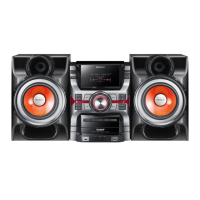
Samsung MAX-N50 Specifications

General IconGeneral
TypeCD Player
Playable MediaCD, CD-R, CD-RW
Audio Output ModeStereo
Tuner Presets30
Remote ControlYes
Tuner BandsFM/AM

Summary

1. Alignment and Adjustments

1-1 Tuner

Procedures for FM and AM tuning adjustments.

1-2 Cassette Deck

Procedures for tape speed, playback level, and bias voltage adjustment.

2. Exploded Views and Parts List

3. Electrical Parts List

4. Block Diagrams

4-1 MAIN Part(COMMON)

Common block diagram for the main section of the unit.

4-2 MAIN Part(Only MAX-N57)

Block diagram specific to the MAX-N57 model's main part.

4-3 CD Part(COMMON)

Common block diagram for the CD playback section.

6. Wiring Diagram

6-1 Wiring Diagram(COMMON)

Overall wiring diagram connecting major PCBs and components.

5. PCB Diagrams

7-1 CD Parts(COMMON)

Schematic diagram for the CD deck section.

7. Schematic Diagrams

7-1 CD Parts(COMMON)

Schematic diagram for the CD deck section.

7-2 MAIN Part (COMMON)

Schematic diagram for the main PCB.

7-3 MAIN Part (Only MAX-N57)

Schematic diagram specific to the MAX-N57 model's main part.

7-4 FRONT(COMMON)

Schematic diagram for the front panel and controls.

7-5 TUNER(COMMON)

Schematic diagram for the tuner section.

Related product manuals