Do you have a question about the Samsung MAX-N75 and is the answer not in the manual?
Details on FM THD, FM Search Level, and AM I.F adjustments.
Step-by-step adjustments for AM, MW, LW, and SW bands.
Procedures for adjusting tape speed and playback level.
List of electrical components for the MAXN72 unit.
List of electrical components for the MAXN75 unit.
Detailed schematic of the CD playback circuitry.
Detailed schematic of the common main circuitry.
Detailed schematic of the common front circuitry.
Detailed schematic of the tuner circuitry.
| Brand | Samsung |
|---|---|
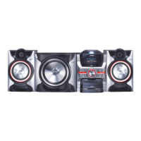
| Model | MAX-N75 |
| Category | CD Player |
| Frequency Response | 20 Hz - 20 kHz |
| Harmonic Distortion | 0.05% |
| Output Level | 2 V |
| Playable Media | CD |