Do you have a question about the Samsung MAX-N57 and is the answer not in the manual?
Procedures for FM and AM tuner alignment, including THD, search level, and band adjustments.
Procedures for adjusting cassette deck tape speed, playback level, and record bias voltage.
Schematic diagram for the CD section of the unit.
Schematic diagram for the common main part of the unit.
Schematic diagram for the main part specific to MAX-N57 models.
Schematic diagram for the common front panel and related circuits.
Schematic diagram for the common tuner section.
| Type | CD Player |
|---|---|
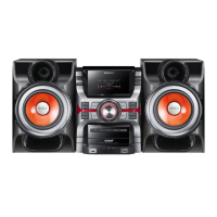
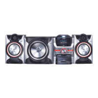
| Brand | Samsung |
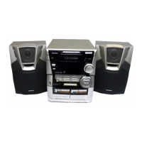
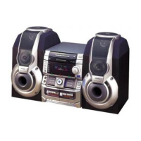
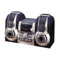
| Model | MAX-N57 |
| Audio Output Mode | Stereo |
| Tuner Bands | AM/FM |
| Preset Station Quantity | 30 |
| Remote Control | Yes |
| Frequency Response | 20 Hz - 20 kHz |
| Playable Media | CD |