Do you have a question about the Samsung MAX-WB650 and is the answer not in the manual?
Procedures for aligning and adjusting the component system's tuner and cassette deck.
Detailed diagrams and lists of parts for various components like cassette deck, CD deck, and speakers.
Comprehensive list of electrical components used in the system, including resistors, capacitors, and ICs.
High-level functional overview of the system's main, CD/MP3, and tuner sections.
Visual layout of the printed circuit boards for the main, front, tuner, CD/MP3, and amplifier sections.
Schematic showing the interconnection of various PCBs and components within the system.
Detailed electronic circuit diagrams for CD, Main, Front, Amplifier, and Tuner sections of the system.
Step-by-step guide for tuning FM and AM frequencies, including IF center and THD adjustments.
Procedures for adjusting AM, LW, SW1, and SW2 bands, including OSC and RF settings.
Procedures for adjusting tape speed, playback level, and bias voltage for the cassette deck.
Steps to calibrate the tape deck's speed using a frequency counter and measuring tape.
Guide for setting the correct playback level for both cassette deck channels.
Detailed parts breakdown and list for the cassette deck module (ADR246AMW).
An overall exploded view of the component system and its associated parts.
An extensive list of components for the entire system, including specifications and remarks.
Breakdown of parts and an exploded view for the CD deck mechanism.
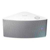
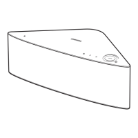
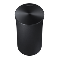
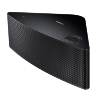
Parts breakdown and exploded views for the speaker systems (MAXWB630/MAXZB630).
Specific parts list and exploded view for the MAXWB630 and MAXZB630 speakers.
Parts list and exploded view for the MAXWB650 speaker system.
Functional block diagram of the main unit, showing signal flow for audio and control.
Block diagram illustrating the CD and MP3 playback sections, including servo and decoder circuits.
Diagram showing the component layout on the main printed circuit board (AH41-00434A).
Component layout diagram for the front printed circuit board.
Component layout diagram for the tuner printed circuit board.
Component layout diagram for the CD/MP3 printed circuit board.
Component layout diagram for the amplifier printed circuit board.
Detailed circuit diagram for the CD player section, showing ICs and component connections.
Circuit diagram for the main unit, detailing power, audio, and control signal paths.
Circuit diagram for the front panel functions, including VFD and controls.
Circuit diagram for the audio amplifier stages, showing power output ICs.
Circuit diagram for the European tuner section, including FM, AM, and RDS functions.
Circuit diagram for the Russian tuner section, including FM, AM, and RDS functions.
Circuit diagram for the 2-band tuner section, covering FM and AM operations.
| Brand | Samsung |
|---|---|
| Model | MAX-WB650 |
| Category | Stereo System |
| Type | Mini Hi-Fi System |
| Number of Discs | 1 |
| Speaker Type | 2-Way |
| Signal-to-Noise Ratio | 70 dB |
| Playable Media | CD, CD-R, CD-RW, MP3 |
| Audio formats supported | MP3 |
| Frequency Response | 20 Hz - 20 kHz |
| Weight | 5.5 kg |