18
Wiring works
0
1
2
3
4
5
6
7
8
9
A
B
C
D
E
F
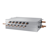
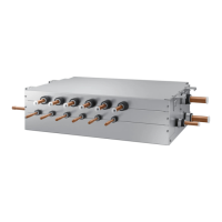
Indoor UnitIndoor Unit
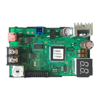
MCU PCB
MCU PCB
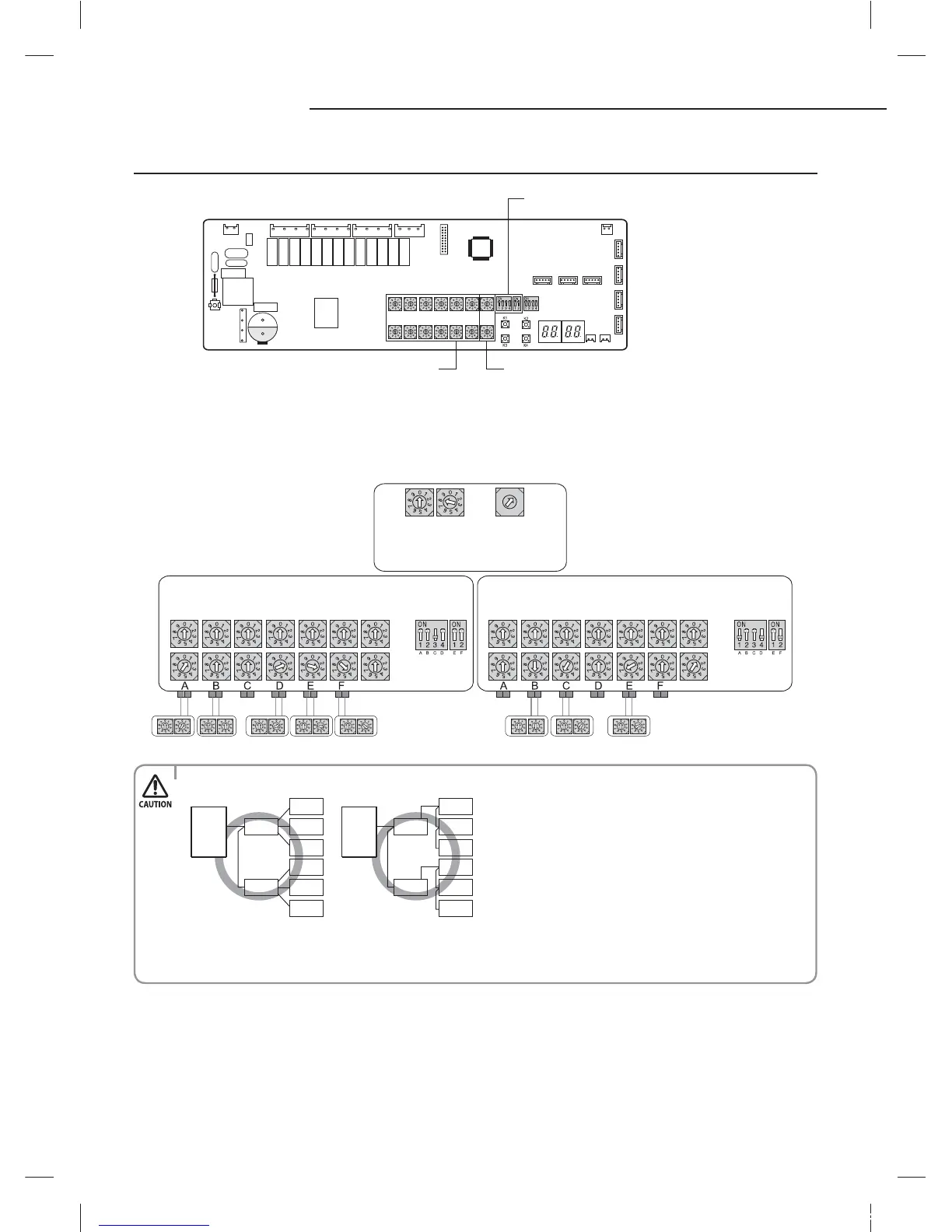
Setting the number
of Indoor Unit
SW51 SW52
Setting the
number of MCU
SW57
Indoor Unit ADDRESS
Outdoor Unit PCB
MCU
ADDRESS
MCU
ADDRESS
Indoor Unit ADDRESSMCU DIP S/W
MCU DIP S/W
Setting MCU option
DIP switch for indoor unit setting (ON:Use, OFF:Not use)
Rotary switch for MCU ADDRESSRotary switch for Indoor unit ADDRESS
• Connect the power cable using the compressed ring terminal.
MCU
MCU
Indoor unit
Indoor unit
Indoor unit
Indoor unit
Indoor unit
Indoor unit
Indoor unit
Indoor unit
Indoor unit
Indoor unit
Indoor unit
Indoor unit
MCU
MCU
• Communication cables are connected as shown above when installing MCU.
• When installing electricity and wires of MCU, please proceed the work refering to the installation manual of the
HR outdoor unit.
X
Address on the rotary switch at the MCU PCB and the rotary switch on the indoor unit must be same.
X
When installing more than 2 MCU’s set each rotary switch of MCU dierently.
X
When the indoor unit connection port on the MCU is not being used, set the corresponding MCU DIP switch to ‘OFF’
outdoor
unit
outdoor
unit
tj|Tz]ullXuptluGWZ[`WhTW]UGGGX_ YWX\TW`TX^GGG㝘㤸GXWa\Za[`
 Loading...