Do you have a question about the Samsung NV24HD and is the answer not in the manual?
Detailed technical specifications of the camera's image sensor, lens, LCD, focusing, shutter, exposure, flash, and more.
Lists the minimum hardware and software requirements for Windows and Macintosh to operate the camera's software.
Outlines the specific system requirements for playing H.264(MPEG4.AVC) video files using QuickTime Player 7.4.
Describes the types of memory cards supported by the camera and their capacities, including write protection features.
Explains the various icons and indicators displayed on the camera's LCD monitor during recording and playback modes.
Illustrates how to connect the camera to various peripherals like computers, card readers, and monitors using different cables.
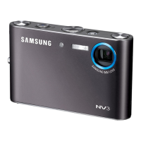
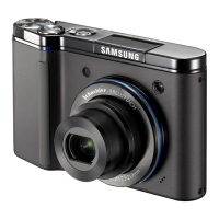
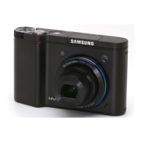
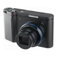
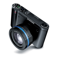
Identifies and labels all external buttons, controls, and features on the front, top, rear, and bottom of the camera.
Introduces the software included with the camera, such as camera drivers, Samsung Master, and QuickTime Player.
Provides step-by-step instructions for installing the necessary camera drivers and software applications on a PC.
Addresses common troubleshooting issues and frequently asked questions related to USB connection problems with the camera.
Shows an exploded view and parts list for the main assembly of the camera, detailing individual components.
Presents an exploded view and parts list for the first part of the camera's body assembly, including numerous sub-components.
Displays an exploded view and parts list for the second part of the camera's body assembly, detailing its constituent parts.
Illustrates the exploded view and parts list for the camera's front cover assembly, showing all related components.
Provides an exploded view and parts list for the camera's back cover assembly, detailing its components.
Shows the exploded view and parts list for the camera's top cover assembly, including all associated parts.
Details the exploded view and parts list for the camera's barrel assembly, which includes the lens mechanism.
Lists and illustrates all the items included in the camera's packaging, such as accessories and documentation.
Explains the procedure to reset the camera to its factory default settings, including important notes about data initialization.
Guides users on how to check the current firmware version installed on the camera using a specific developer mode.
Provides detailed steps for upgrading the camera's firmware, including prerequisites like battery level and file requirements.
Outlines the firmware upgrade procedure specifically for the camera's slide button functionality.
Details the firmware upgrade process for the Optical Image Stabilization (OIS) module, with subsequent centering adjustment.
Provides essential precautions and information regarding the adjustment processes, script files, and their purpose.
Explains how to back up and restore camera adjustment settings, crucial when replacing the main board.
Describes the procedure for centering the Optical Image Stabilization (OIS) module, a critical adjustment step.
Details how to test the camera's battery level using specific scripts and analyze the results.
Explains the process of adjusting the CCD gain to minimize differences in saturation levels between cameras.
Describes how to adjust the mechanical shutter's closing delay time to ensure proper brightness in high-speed modes.
Details the procedure to adjust lens shading, which compensates for darker image edges by increasing brightness.
Outlines the process for adjusting flash performance and checking for hardware or software faults using a flash test.
Explains how to compensate for white balance deviations when the camera is flashing, performed after flash exposure adjustment.
Describes the PUNT adjustment, which compensates for lens assembly differences to improve auto-focus performance.
Details a test procedure involving repeated use of camera functions to detect hardware or software defects.
Explains how to test for defective pixels on the CCD sensor and the criteria for determining a good or bad CCD.
Describes the procedure to adjust the CCD black level (optical black) to compensate for differences in sensor characteristics.
Outlines how to adjust the slide button's recognition threshold to resolve potential operational issues.
Shows the component arrangement and layout on the camera's main top PCB.
Displays the component arrangement and layout on the camera's main bottom PCB.
Details the circuit diagram for the main sub-connector, showing pin assignments and connections.
Illustrates the pre-layout of the main circuit board, showing component placement and trace routing.
Presents the circuit diagram for the Analog Front End (AFE) block, handling signal conditioning.
Shows the circuit diagram related to the camera's memory components and their connections.
Details the circuit diagram for the microcontroller (MICOM) unit, the camera's central processing component.
Provides the circuit diagram for the motor control systems within the camera.
Shows circuit diagrams for the external interface and HDMI connection, including pinouts.
Details the circuit diagram for the power management integrated circuit (IC), responsible for power distribution.
Presents the circuit diagram for the AMOLED LCD display interface.
Shows circuit diagrams for the top connector and the strobe flash connector.
Details the circuit diagram for the card interface communication.
Provides critical safety precautions and warnings for handling electronic components and performing disassembly.
Offers step-by-step instructions and visual guides for safely disassembling the camera.
| Megapixel | 10.2 MP |
|---|---|
| Camera type | Compact camera |
| Sensor type | CCD |
| Image stabilizer | Yes |
| Image sensor size | 1/2.3 \ |
| Maximum image resolution | 3648 x 2736 pixels |
| Digital zoom | 5 x |
| Optical zoom | 3.6 x |
| Focal length range | 4.3 - 15.5 mm |
| Interface | USB |
| Digital SLR | No |
| Minimum RAM | 256 MB |
| Power source | SLB-1137D |
| Camera shutter speed | 1 - 1/2000 s |
| Minimum storage drive space | 250 MB |
| Compatible operating systems | Windows 98SE/2000/ME/XP/VISTA Mac OS 10.2 |
| Focal length (35mm film equivalent) | 24 - 86.5 mm |
| Auto focusing (AF) modes | centre weighted auto focus, multi point auto focus |
| Macro focusing range (tele) | 0.5 - 0.8 m |
| Macro focusing range (wide) | 0.05 - 0.8 m |
| Internal memory | 16 MB |
| Compatible memory cards | mmc, sd |
| Motion JPEG frame rate | 30 fps |
| Maximum video resolution | 1280 x 720 pixels |
| Display diagonal | 2.5 \ |
| Display resolution (numeric) | 230000 pixels |
| USB version | 2.0 |
| Product color | Black |
| Scene modes | Backlight, beach, Children, Close-up (macro), Documents, dusk, Fireworks, Night, Portrait, Sunset, Underwater, Landscape (scenery) |
| Image editing | resizing, rotating, trimming |
| Photo effects | black&white, Negative film, Sepia, Vivid |
| White balance | auto, Cloudy, custom modes, daylight, Fluorescent, Tungsten |
| Camera playback | movie, single image, slide show, thumbnails |
| Battery capacity | 1000 mAh |
| Operating temperature (T-T) | 0 - 40 °C |
| Storage relative humidity (H-H) | 5 - 85 % |
| Flash modes | auto, fill-in, Flash off, Red-eye reduction, Slow synchronization |
| Light metering | Spot |
| Light exposure modes | Manual |
| Camera shutter type | electronic, mechanical |
| Depth | 18.95 mm |
|---|---|
| Width | 98.5 mm |
| Height | 61 mm |
| Weight | 145.5 g |