Do you have a question about the Samsung NX58H9500WS/AA and is the answer not in the manual?
Overview of the service manual's purpose and scope for technicians.
Essential safety measures required for servicing the appliance to prevent harm.
Critical instructions to prevent death, injury, fire, or property damage during use and servicing.
Safety guidelines and precautions specific to the self-cleaning oven function.
Identifies locations for model/serial number labels and technical sheets for service reference.
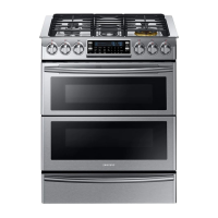
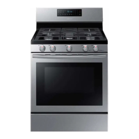
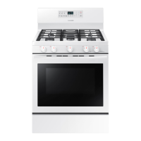
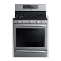
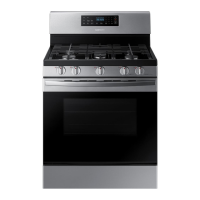
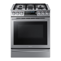
Details the key features and components of the oven section of the appliance.
Explains the functions and layout of the oven's main control panel interface.
Describes the functions and operation of the gas cooktop control panel.
Presents a comprehensive table detailing the appliance's technical specifications.
Lists and describes the included accessories with their respective code numbers for identification.
Lists essential tools required for appliance disassembly and reassembly procedures.
Step-by-step guide for disassembling and reassembling the convection motor cover.
Procedure for removing and reinstalling the appliance's main control box assembly.
Instructions for disassembling and reassembling the cooktop frame assembly.
Guide for removing and reinstalling the appliance's side panel.
Steps for disassembling and reassembling the appliance's burner box assembly.
Procedure for replacing the PCB assembly and the cooktop frame.
Guide for disassembling and reassembling the display and rotary switch components.
Steps for removing and replacing the ignition electrode assembly.
Instructions for removing, replacing, and checking the burner cup for gas leakage.
Procedure for removing and installing the gas orifice nozzle for burner adjustment.
Guide for replacing the cooktop valve and checking for gas leakage post-replacement.
Steps for removing and replacing the ignition switch for the burners.
Procedure for disassembling and replacing the motor and thermal cut-off (TCO).
Guide for removing, replacing, and testing the appliance's door latch assembly.
Steps for removing and replacing the oven temperature probe assembly.
Procedure for removing and replacing the oven door plunger switch.
Instructions for replacing the oven light bulb and its cover.
Guide for removing and replacing the oven temperature sensor (thermistor).
Steps for removing and installing the oven door gasket, ensuring a proper seal.
Procedure for safely removing and reinstalling the oven door assembly.
Guide for disassembling and replacing the oven door handle and inner glass panel.
Steps for removing and replacing the appliance's power cord assembly.
Procedure for disassembling and replacing the broil burner assembly.
Instructions for replacing the broil burner's HSI, nozzle, and holder components.
Guide for disassembling and replacing the bake burner assembly.
Instructions for replacing the bake burner's HSI, nozzle, and holder components.
Procedure for removing and reinstalling the warming drawer assembly.
Steps for removing and replacing the warming drawer heater element.
Guide for disassembling and replacing the convection motor assembly.
Procedure for removing and replacing the convection heater component.
Instructions for removing the appliance's bracket cavity assembly.
Guide for replacing the safety valve assembly, including gas line disconnection and reconnection.
Steps for removing and replacing the cover motor component.
Explains how to check and interpret oven error codes displayed on the control panel.
Troubleshooting guide for issues related to the control panel and its associated parts.
Troubleshooting procedures for common issues encountered with the oven components.
Troubleshooting guide for problems encountered with the warming drawer functionality.
Illustrations showing the physical layout of the main and display PCB boards.
Explains the functionality and interaction of the touch control panel keypad interface.
Details the function and role of each component on the main PCB.
Explains the function and role of each component on the display PCB.
Provides a schematic diagram illustrating the electrical connections of the appliance.
Lists diagnostic checkpoints and remedies to perform before initiating service or repairs.
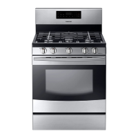
| Type | Freestanding |
|---|---|
| Fuel Type | Gas |
| Oven Capacity | 5.8 cu. ft. |
| Cooktop Surface | Stainless Steel |
| Number of Burners | 5 |
| Convection Oven | Yes |
| Self-Cleaning | Yes |
| Color | Stainless Steel |
| Dimensions (W x D) | 29.9 x 28.5 inches |
| Width | 29.9 inches |
| BTU | 18, 000 |