J
Jim HughesAug 3, 2025
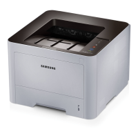
What to do if the output tray is full or paper is jammed in the exit area of my Samsung ProXpress M453x?
- JJacob RobinsonAug 3, 2025
If the output tray of your Samsung Printer is full or paper is jammed in the exit area, gently pull the paper out of the output tray.