53
OPERATION PRINCIPLES BY PARTS OF CIRCUIT
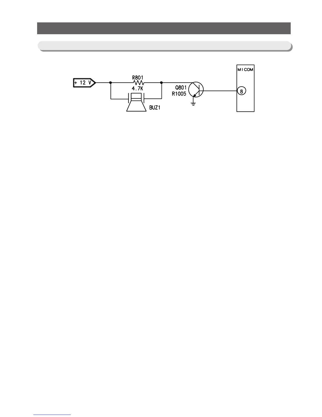
11-10) Buzzer Circuit Diagram
1) The circuit is composed of like the above and MICOM controls the alarm function with 2KHz.12V is
always applied to the circuit.So,when MICOM sends alarm signals to Q801 Transistor Bass,the
transistor is turned on applying 12V to the buzzer,which operates the buzzer. 4.7Kohm of R801 is a
resistance for the production of quality buzzer sound.