RESET
D101-104
In4007
C105
104
C101
1000uF
7
5
18
21
C202
104
Ic02
5195A
I
G
O
Vcc
C203
104
VSS/ASS
17
C801
104
C105
104
C802
104
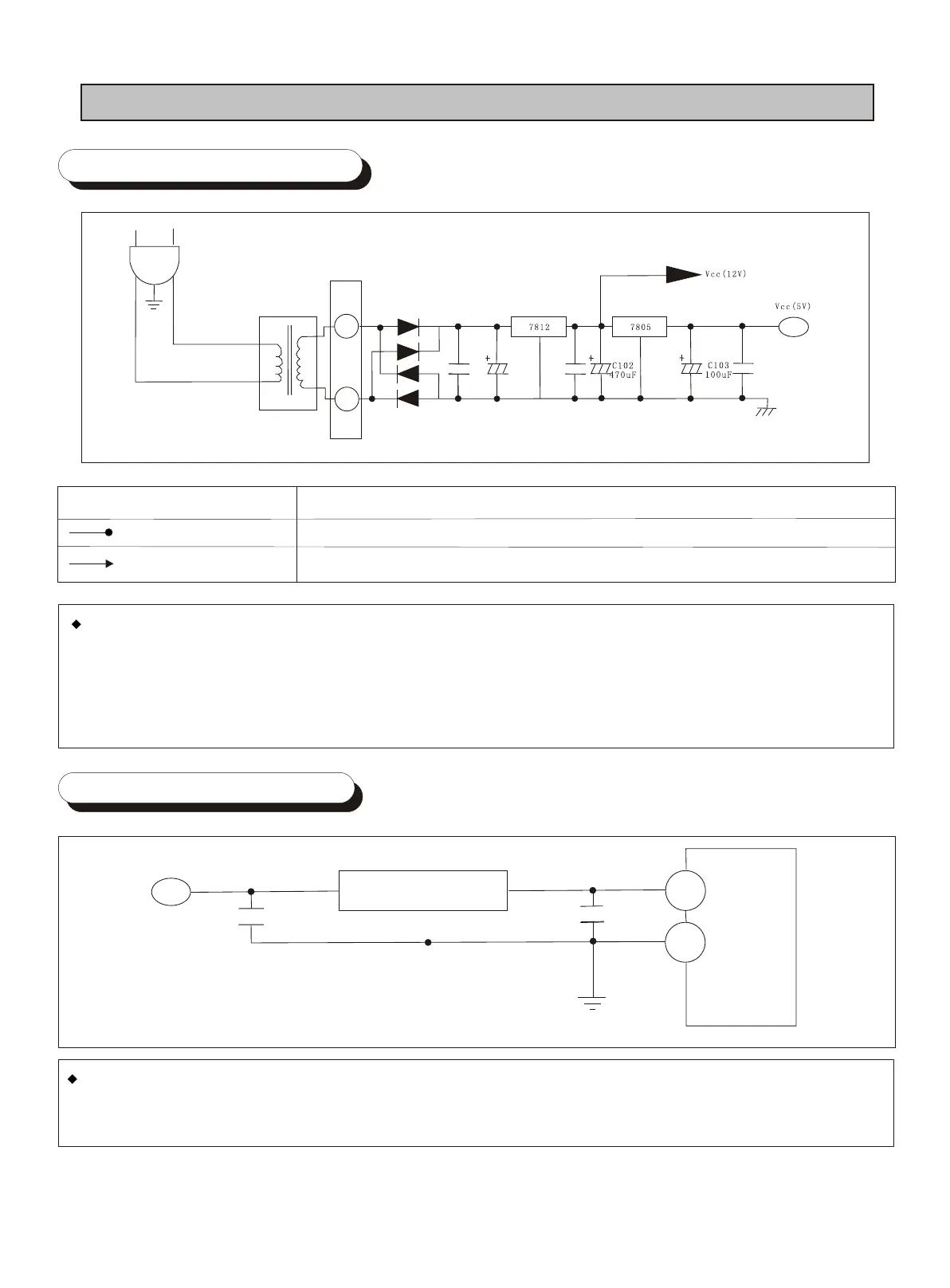
6. CIRCUIT DETAILS
6-1 Power Supply Part
Power supply
Vcc (DC 5V)
Vcc (DC 12V)
Applied circuit
Chip peripheral circuit and sensor
Control voltage of the display and relay
The AC input voltage will be stepped down by the transformer and be converted into the DC voltage
by the rectifying circuit (D101-104). The 1000F/35V wave filter capacitor will be used to filter out the
residue AC voltage and the manostat 7812 is used to output the steady 12V DC voltage that will be
used as the control voltage of the relay and display. The 12V DC voltage will be regulated by the
manostat 7805 to output the steady 5V voltage, which will be used as the output voltage of the chip
peripheral circuit and various signals (sensor, switch) .
6-2 Reset Circuit Part
The reset circuit part enables the system program to return the system that meets power trouble
or abrupt power-off to the initial state by the memory of the core chip. At the very beginning of
the power-on, the reset chip voltage is LV, and becomes HV after normal operation.