Buzzer
R801
4.7K
DC 12V
35
MICOM
19
5
12
1
5
7
9
RY72
RY71
NC
NO
Rc71
RY74
CON71
RED
3
6
4
13
11
14
38
6
5
4
+12V
Ic05
3
1
3
2
15
1
16
RY74
1
Rc72
Rc73
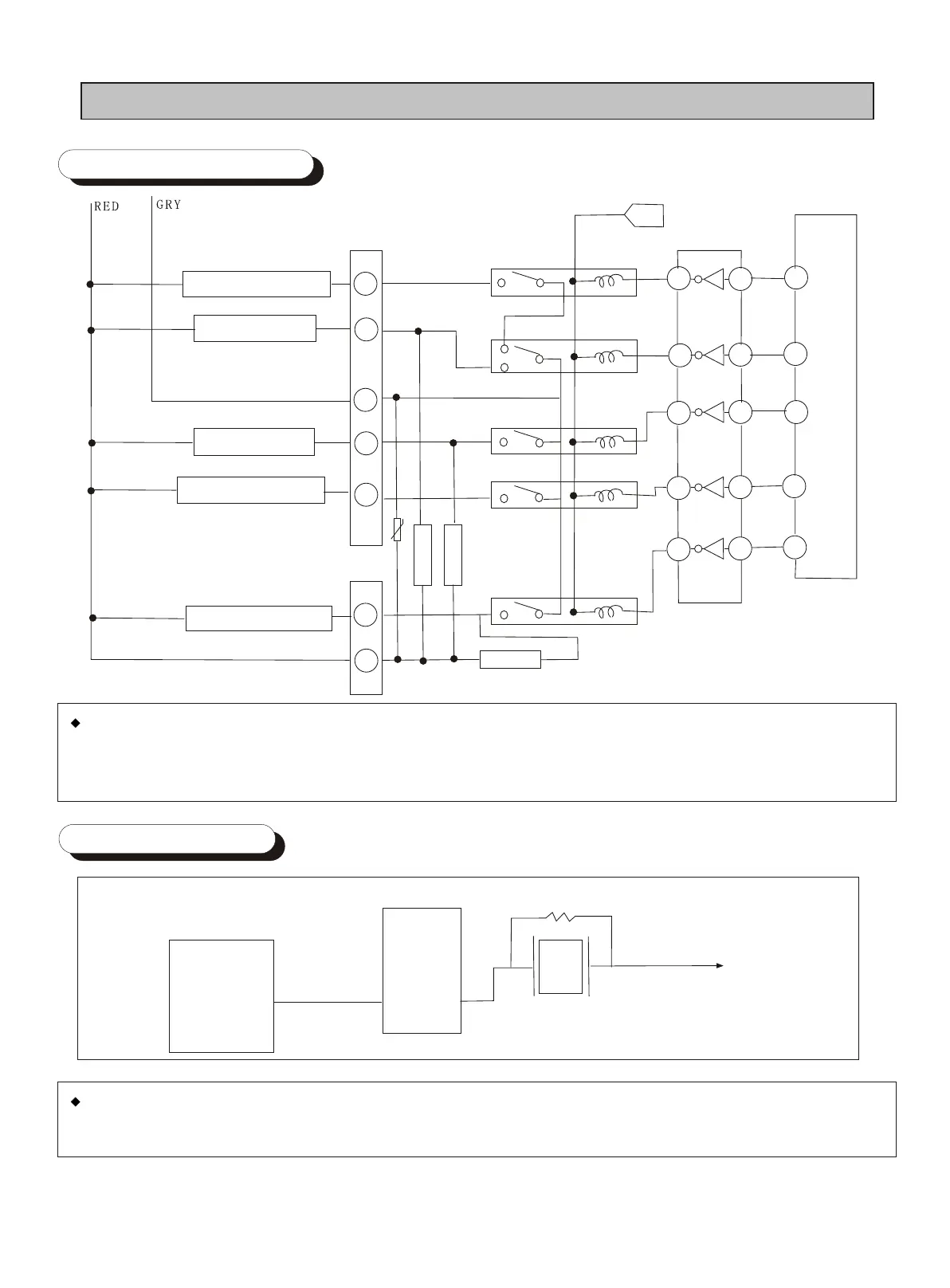
6-5 Operation Part
Core chip
Defrost Heater
Compressor
Fan motor
Inside lamp
Gear motor
If outputing the relevant work circuit signals into the core chip port, the driving chip (ULN2003) will
be activated. The DC 12V voltage will set the relay terminals to the position of On due to relay coils
reaction to activate the circuit.
6-6 Buzzer Part
The driving chip is initiated by the core chip generated CLOCK and impose the 12V volgtage on
the buzzer to make it voice a sound.