11. Installation
56
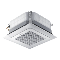
2 Use a standard 2-5-inch (65-mm) hole saw to drill one
hole at the selected location, at a 15° downward angle
so that the drain hose will drain properly.
Drain hose
Wall
Indoor unit
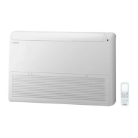
3 Based on the hole location, determine where the
piping bundle (drain hose, refrigerant pipes, and
cables) will exit the unit.
Left
Right
bottom
Rear right or left
<Front view>
<Side view>
NOTE
• The left, right, or bottom exit will only be used if the
hole is not positioned behind the unit.
Connecting the power and communication cables
Ã˙Їϑ˝ɇЇϩϑцϑϩʪࡥϑϩɇɇϑʒʪϑʀθɵʪʒϩ˵ʪ
installation manual supplied with the outdoor unit.
WARNING
• Do not modify the power cable in any way. Doing so
may cause electric shock or fire due to poor connection,
poor insulation, or current limit override. Make sure
to comply with the technical standards of electrical
installations and the wiring regulations in the local area.
• This appliance must be properly grounded. Do not
ground the appliance to a gas pipe, plastic water pipe,
or telephone line. Failure to comply may result in
electric shock, fire, and explosion.
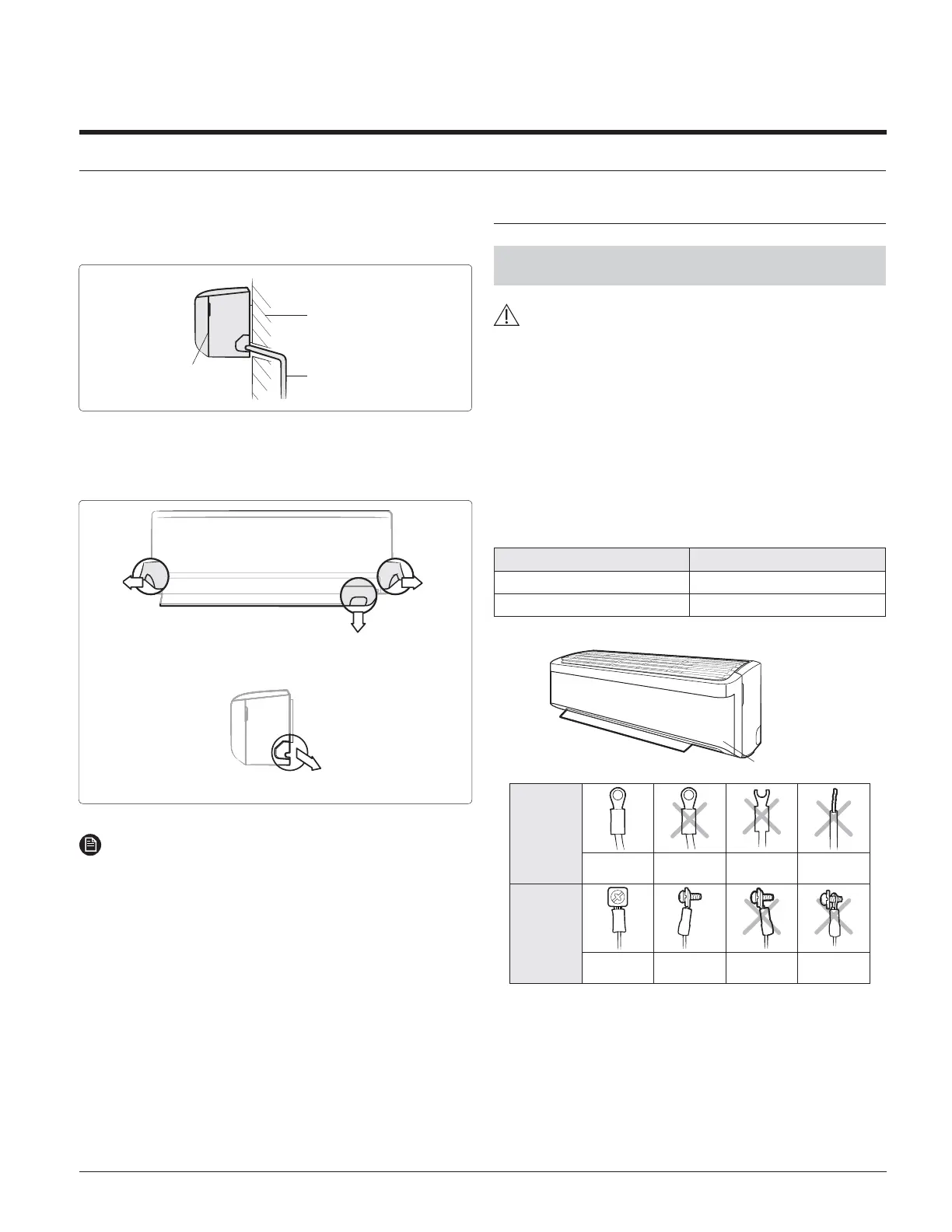
1 Connect each wire to its corresponding terminal number.
Cable Terminals
Power cable L1, L2, ground
Communication cable F1, F2
Control box
Before
connecting
Correct
Upside
down
Damaged
Non-
circular
After
connecting
Correct
(Front view)
Correct
(Side view)
Upside
down
Non-fitted
<Circular terminal>
Indoor Unit Installation
 Loading...