96
6. PCB DIAGRAM
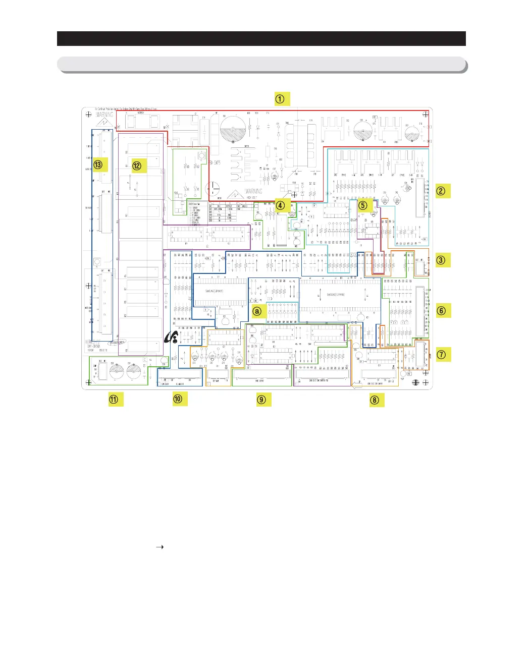
6-6) PART ARRANGEMENT (Main Board)
1. SMPS Circuit: With input AC voltage, it outputs DC12V and 5V.
2. It supplies 8.0V~12V to Deodorizer & Fan Motors.
3. Dispenser Ice & Water S/W
4. Buzzer
5. EEPROM : Data Storing
6. Receives various sensor voltages and door operation signals, and filter their noises.
Then, send them to MICOM.
7. PLC Circuit (PLC Input/Output) - PLC (Power Line communication)
8. Damper and Heater
9. Display Control (MAIN
PANEL PCB)
10. Ice-Maker Kit Control
11. PCB & Inverter Comp Driver: DC12V, 5V and GND are input (Applied to Inverter Model).
12. AC Load Control Relay - It operates with Micom driving signals being receipt through Sink IC.
13. AC Load Connector
a. Diode Option Setting
 Loading...