Samsung Electronics 5-1
5. Alignment and Adjustment
5-1 Mechanical Adjustment
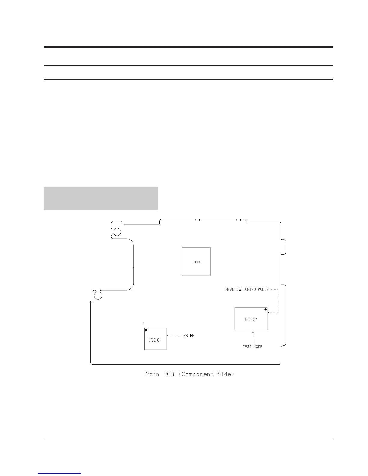
Test Point :
PB RF - Pin 45 of IC201
Head Switching Trigger - Pin 96 of IC601
Fig. 1 The location of test point
* Note 1 : Mechanical alignment is performed for the linearity of PB-RF(Envelope).
* Note 2 : Refer to the mechanism manual ÒDE-6Ó(AD68-30200A) for the mechanism alignment.
1) Short between pin #67 of IC601 and GND in order to set the TEST MODE.(ThatÕs Track Shift Mode)
2) Connect the Head SW Pulse in CH1 and the PB-RF in CH2 to oscilloscope.
3) Refer to the Fig1 for the location of test point.
4) Play the alignment tape supplied, and fit the PB-RF form like as Fig1.
(Refer to the alignment manual of the DE-6 described above).
5) If the alignment is completed, then remove the short wire for the release of the test mode.