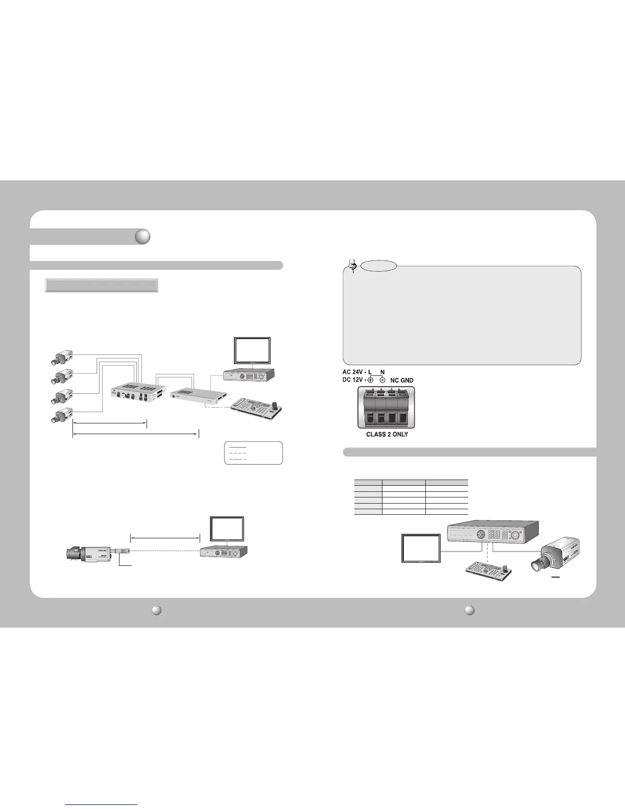
300m(1000ft) or Less
900m(3000ft) or Less
SCC-3100A
SUB-2000
RS-485
SPU-400T
SPU-400R
VIDEO
UTP CABLE
BNC CABLE
RS-485
UTP Power Supply Link Setup
•Usingtheproductwiththird-partyUTPperipheralsmayresultindegradationofproduct
function and performance.
•Attenuationanddistortioninsignalmayoccurifthemaximumtransmissiondistanceis
exceeded.Pleasenotethatdependingonthe installation environment/condition,the
signal may become attenuated and distorted and cause the camera to function
incorrectly even when the transmission distance is within the maximum.
•IfusingRS-485communication, please use the SAMSUNG-T, SAMSUNG-E, PELCO-D,
PELCO-P, BOSCH, HONEYWELL, VICON and PANASONIC Protocol.
•If you areusingthe1ChPassiveReceiversystemsetup,pleaseconnecttheadapter
(AC24VorDC12V)directlytothecamera.
Notes
If the distance between the camera and the Power Supply exceeds
300m(1000ft), please connect an AC 24V or DC 12V adapter to the
Power Input Terminal Block(Accessory). Impressing power when
the maximum transmission distance is exceeded may result in
degradation of picture quality or even camera failure.
1. SUB-2000 4CH Power Supply 4Ch Receiver DVR/Monitor/Controller
The maximum power transmission distance for the camera is 300m(1000ft), and the
distance between the camera and the 4ch Receiver cannot exceed 900m(3000ft).
2. UTP Receiver Link Setup(Additional Power input is needed)
SUB-2000
1Ch Passive Receiver
DVR
Monitor
1Ch Passive Receiver
225m(750ft) or Less
System Diagram
• Coaxial Communications System
• OSD Control method
Using Coaxial Communications
CAMERA DVR CONTROLLER
SET MENU/ENTER OSD KEY
UP UP KEY JOYSTICK UP
DOWN DOWN KEY JOYSTICK DOWN
LEFT LEFT KEY JOYSTICK LEFT
RIGHT RIGHT KEY JOYSTICK RIGHT


 To Next Page