T
Tammy AndersonAug 5, 2025
How to troubleshoot Samsung WF22H6300AG/AX motor power?
- Ccarmen72Aug 5, 2025
To troubleshoot the motor power of your Samsung Washer, check if the motor power (Blue, White, Red) wire is properly connected.
How to troubleshoot Samsung WF22H6300AG/AX motor power?
To troubleshoot the motor power of your Samsung Washer, check if the motor power (Blue, White, Red) wire is properly connected.
Essential safety guidelines for service technicians during operation.
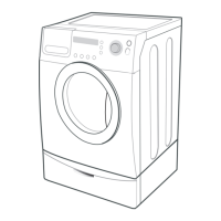
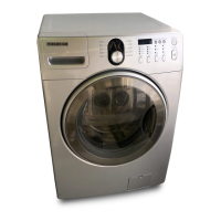
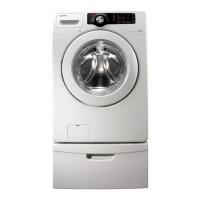
Details of the washing machine's key features and their benefits.
Technical data and measurements for the washing machine models.
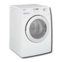
Comparison table of current models against older Samsung washing machines.
Specifications and details for optional accessories like pedestals and stacking kits.
A list of specialized tools required for servicing the washing machine.
Illustrated step-by-step guides for disassembling various parts of the washing machine.
A comprehensive list of error codes with their potential causes.
Detailed procedures to resolve specific error codes displayed by the washer.
Identification and layout of components on the main printed circuit board.
Electrical schematics for key sections of the main PCB.
Identification and layout of components on the inverter printed circuit board.
Electrical schematics for key sections of the inverter PCB.
Identification and layout of components on the sub printed circuit board.
Electrical schematics for key sections of the sub PCB.
Complete schematic illustrating all electrical connections within the washing machine.
Explanation of the model naming structure and project code meanings.
| Brand | Samsung |
|---|---|
| Model | WF22H6300AG/AX |
| Type | Front Load Washer |
| Energy Star Certified | Yes |
| Spin Speed | 1300 RPM |
| Steam Function | Yes |
| Number of Wash Cycles | 12 |
| VRT Technology | Yes |