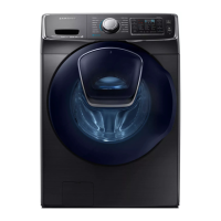
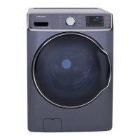
36 _ PCB Diagram
5-4. CONNECTOR PORT PART DETAILED MANUAL-SUB PCB (WF520ABP/XAA, WF520ABW/XAA)
► CN10
1. JOGsignal
2. JOGsignal
3. Ground
4. Ledsignal
5. Ledsignal
6. Ledsignal
7. Ledsignal
8. Ledsignal
9. Ledsignal
10.Ledsignal
11.Ledsignal
12.Buzzersignal
13.Buzzersignal
► CN2
1. Drumlight
2. 15V
► CN10
1. CommunicationsPort(Rx)
2. CommunicationsPort(Tx)
3. ResetSignalouput
4. 5V
5. Ground
6. 15V
7. MainresetsignalfromSUB
8. WaterlevelsignalfromSUB
9. WatchdogsignalfromSUB
10. Empty pin
► CN10
1. Dooropen/closesingnal
2. Empty pin
3. Empty pin
4. Watertemperaturesignal
5. Ground
6. Waterlevelsignal
7. Waterlevelsignal
8. Empty pin
 Loading...

