S&C ELECTRIC COMPANY
s
INSTRUCTION SHEET
716-501
Page 13 of 26
August 12, 2002
INSTALLATION — Continued
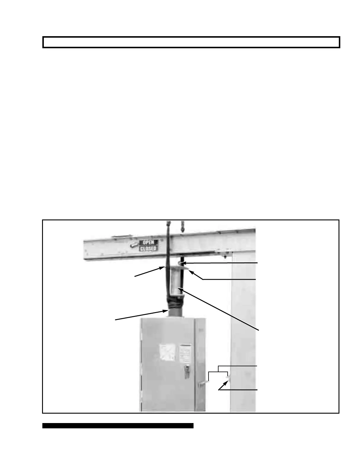
Figure 6. Hoisting operator into position.
Step 10
Attach the operator support angle to the appropriate
mounting pedestal using two ⁵⁄₈—1114 hex-head galva-
nized steel cap screws, four flat washers, and two self-
locking hex nuts furnished. Refer to the catalog drawing
and Figure 6. Then attach the operator support plate to
the angle on the side of the operator enclosure and to the
operator support angle on the mounting pedestal using
four ¹⁄₂—131¹⁄₂ hex-head galvanized steel cap screws,
flat washers, and self-locking hex nuts furnished. Securely
tighten the screws. See Figures 1 and 6. On Circuit-
Switchers utilizing two or three mounting pedestals,
insert the hole plugs furnished into all unused holes in the
pedestals.
Step 11
Attach the support arms to the mounting pedestals as
shown on the catalog drawing, using ⁵⁄₈—111¹⁄₂ hex-
head galvanized steel cap screws and flat washers fur-
nished. The screws should only be loosely attached at this
time.
Step 12
For Circuit-Switchers rated 69 kV through 138 kV: Refer
to the catalog drawing and attach the interrupter-end and
disconnect-end support arm channel assemblies
to the
support arms, using clip angles, ¹⁄₂—131³⁄₄ hex-head
galvanized steel cap screws, flat washers, and self-locking
hex nuts furnished.
For Circuit-Switchers rated 161 kV and 230 kV: Refer to
the catalog drawing and attach the interrupter-end and
disconnect-end support arm channel assemblies to the
support arms, using clip angles, ¹⁄₂—131³⁄₄ hex-head
galvanized steel cap screws (at the outboard pole-units),
¹⁄₂—132 hex-head galvanized steel cap screws (at the
center pole-unit), flat washers, and self-locking hex nuts
furnished.
Level the support arm channel assemblies to the same
elevation as the cross base, then tighten the associated
cap screws securely. Now securely tighten the
⁵⁄₈—111¹⁄₂ hex-head galvanized steel cap screws which
attach the support arms to the mounting pedestals.
Torque the cap screws to 160 foot-pounds.
A single support arm and support arm channel assembly are used on
69-kV Circuit-Switchers with 48-inch phase spacing, for attachment at the
interrupter end. Further, a disconnect-end support arm angle is furnished
in lieu of a disconnect-end support arm channel assembly.
Operator support tube
mounting plate
Uni-ball coupling
Operator support tube
Stored-energy housing
Holes for ¹⁄₂—131³⁄₄
hex-head galvanized steel
cap screws, flat washers,
and self-locking nuts
⁵⁄₈—1114 hex-head
galvanized steel cap
screws, flat washers, and
self-locking nuts
Operator support angles
 Loading...


