S&C ELECTRIC COMPANY
s
716-501
INSTRUCTION SHEET
Page 14 of 26
August 12, 2002
S&C Series 2000 Circuit-Switchers Model 2010 — With Horizontal Interrupters and
Outdoor Transmission (69 kV through 230 kV) Vertical-Break Power-Operated Disconnect
INSTALLATION — Continued
Step 13
For Circuit-Switchers rated 69 kV through 138 kV: Attach
four suitable lifting slings to the channel base of the pole-
unit that will be mounted at the center of the cross
base—marked “Pole 2”—as shown in Figure 7 (left).
(“Pole 2” is positioned outboard on the shipping skid for
ease in handling.)
For Circuit-Switchers rated 161 kV and 230 kV: Attach
the lifting angles retained from Step 1 to the channel base
of the pole-unit that will be mounted at the center of the
cross base—marked “Pole 2,” using ¹⁄₂—131³⁄₄ hex-
head galvanized steel cap screws, flat washers, and hex
nuts furnished. See Figure 7 (right). Securely tighten the
cap screws. (“Pole 2” is positioned outboard on the ship-
ping skid for ease in handling.) Then attach four suitable
lifting slings (10 to 12 feet long for Circuit-Switchers rated
161 kV, 12 to 14 feet long for Circuit-Switchers rated 230
kV) to the lifting angles.
Make certain that the rigging does not stress the inter-
rupter, transition box, or disconnect. Unbolt the base
from the skid. Raise the pole-unit a few feet, then remove
the two ¹⁄₂—131³⁄₄ hex-head galvanized steel cap
screws, flat washers, and hex nuts which attach the ship-
ping bracket to the bottom of the pole-unit channel base.
Note: The insulated operating rod is under pressure;
removal of the two screws may result in the operating rod
quickly moving down approximately ³⁄₈ inch. Remove the
¹⁄₂-inch silicon-bronze pin and cotter pin from the insu-
lated operating rod and retain these for re-use in Step
16(d). Discard the shipping bracket and associated hard-
ware.
Remove the protective cover on the cross base at the
pole-unit mounting position. See Figure 4. Now continue
to raise the pole-unit to its mounting position at the center
of the cross base, as shown on the catalog drawing. Care-
fully guide the pole-unit to avoid damaging the insulated
operating rod. Do not attempt to lift the pole-unit by the
interrupter or disconnect.
Attach the pole-unit channel base to the cross base,
using ¹⁄₂—131³⁄₄ hex-head galvanized steel cap screws,
flat washers, and self-locking hex nuts furnished. Securely
tighten the cap screws.
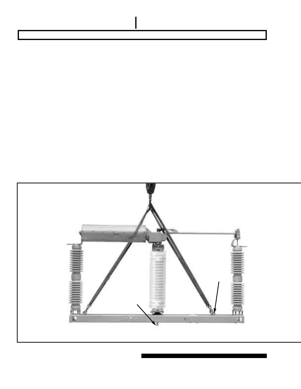
Figure 7. Hoisting the pole-unit.
Insulated operat-
ing rod
(shipping bracket
removed in photo)
Circuit-Switchers rated 69 kV through 138 kV
Eyebolts
(not furnished)
 Loading...


