S&C ELECTRIC COMPANY
s
INSTRUCTION SHEET
716-501
Page 15 of 26
August 12, 2002
INSTALLATION — Continued
Next, attach the pole-unit channel base to the inter-
rupter-end support arm channel assembly. For Circuit-
Switchers rated 69 kV through 138 kV: Use ¹⁄₂—131¹⁄₂
hex-head galvanized steel cap screws, flat washers, and
self-locking hex nuts furnished. For Circuit-Switchers
rated 161 kV and 230 kV: Use ¹⁄₂—132 hex-head galva-
nized steel cap screws, flat washers, and self-locking hex
nuts furnished. Securely tighten the cap screws.
Finally, attach the pole-unit channel base to the discon-
nect-end support arm channel assembly.
For Circuit-
Switchers rated 69 kV through 138 kV: Use ¹⁄₂—131¹⁄₂
hex-head galvanized steel cap screws, flat washers, and
self-locking hex nuts furnished. For Circuit-Switchers
rated 161 kV and 230 kV: Use ¹⁄₂—132 hex-head galva-
nized steel cap screws, flat washers, and self-locking hex
nuts furnished. Securely tighten the cap screws. Shims are
furnished and should be installed as necessary between
the pole-unit channel base and the disconnect-end sup-
port arm channel assembly, to compensatae for any irreg-
ularities between the mating surfaces.
Step 14
Repeat Step 13 for the two outboard pole-units—marked
“Pole 1” and “Pole 3.”
Step 15
For 69-kV Circuit-Switchers with 48-inch phase spacing:
Relevel the interrupter-end support arm channel assembly
and disconnect-end support arm angle to the same eleva-
tion as the cross base. If necessary, loosen the cap screws
used to attach the outboard pole-unit channel bases to the
cross base, interrupter-end support arm channel assem-
bly, and disconnect-end support arm angle, and shift the
pole-units in order to level the channel assembly and sup-
port arm angle. Then securely tighten the cap screws.
Disconnect-end support arm angle on 69-kV Circuit-Switchers with
48-inch phase spacing.
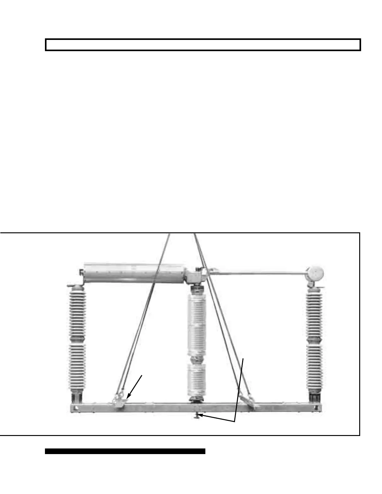
Circuit-Switchers rated 161 kV and 230 kV
Insulated operating rod
(shipping bracket removed
in photo)
Lifting
angles
 Loading...


