S&C ELECTRIC COMPANY
s
716-501
INSTRUCTION SHEET
Page 16 of 26
August 12, 2002
S&C Series 2000 Circuit-Switchers Model 2010 — With Horizontal Interrupters and
Outdoor Transmission (69 kV through 230 kV) Vertical-Break Power-Operated Disconnect
INSTALLATION — Continued
Step 16
Prepare the insulated operating rod of each pole-unit for
attachment to the interphase drive in the cross base as fol-
lows:
(a) Remove the six ⁵⁄₁₆—18³⁄₄ hex-head stainless-steel
cap screws used to attach the access cover to the side
of the transition box. See Figure 8 (left). Remove the
cover and place it and the hardware on a clean sur-
face.
(b) Check that the transition lever is in the open position.
The lever should be turned fully counterclockwise.
See Figure 8 (right). If the lever is not in the open posi-
tion, complete the following steps:
Carefully turn the transition lever to this position. If
the transition lever cannot be freely rotated to its fully
counterclockwise position, misalignment of the inter-
phase drive is occurring in the cross base. Temporarily
swing the insulated operating rod end links up, away
from the interphase drive linkage lever, and again try
Ç
CAUTION
Keep fingers clear of the transition lever’s
travel. The transition lever is under pressure and
could quickly rotate counterclockwise. Injury to the
fingers could result.
rotating the transition lever to its fully counterclock-
wise position; see Figure 9.
(c) Remove the ³⁄₈-inch stainless-steel connecting pin used
to attach the transition lever to the operating rod link.
See Figure 8 (right). The pin is locked in place by a
retainer; lift and turn the retainer to remove the pin.
Keep the pin for re-use in Step 16(e).
(d) Attach the insulated operating rod end links to the
interphase drive linkage lever in the cross base, using
the ¹⁄₂-inch silicon-bronze pin and cotter pin retained
from Step 13; see Figure 9. The insulated operating rod
may be moved up or down, as required, to make the
connection.
(e) Replace the ³⁄₈-inch stainless-steel connecting pin
retained from Step 16(c). See Figure 8 (right). It will
be necessary to loosen the ⁵⁄₁₆—182¹⁄₄ hex-head
stainless-steel screw indicated in Figure 8 (right)
and withdraw it approximately ¹⁄₈ inch, so that the
connecting pin can be inserted. Do not remove the
screw at this time.
(f) After the connecting pin has been inserted and locked
in place by its retainer, remove and discard the
⁵⁄₁₆—182¹⁄₄ hex-head stainless-steel screw and stop
bracket (marked with a black/yellow striped label)
illustrated in Figure 8 (right).
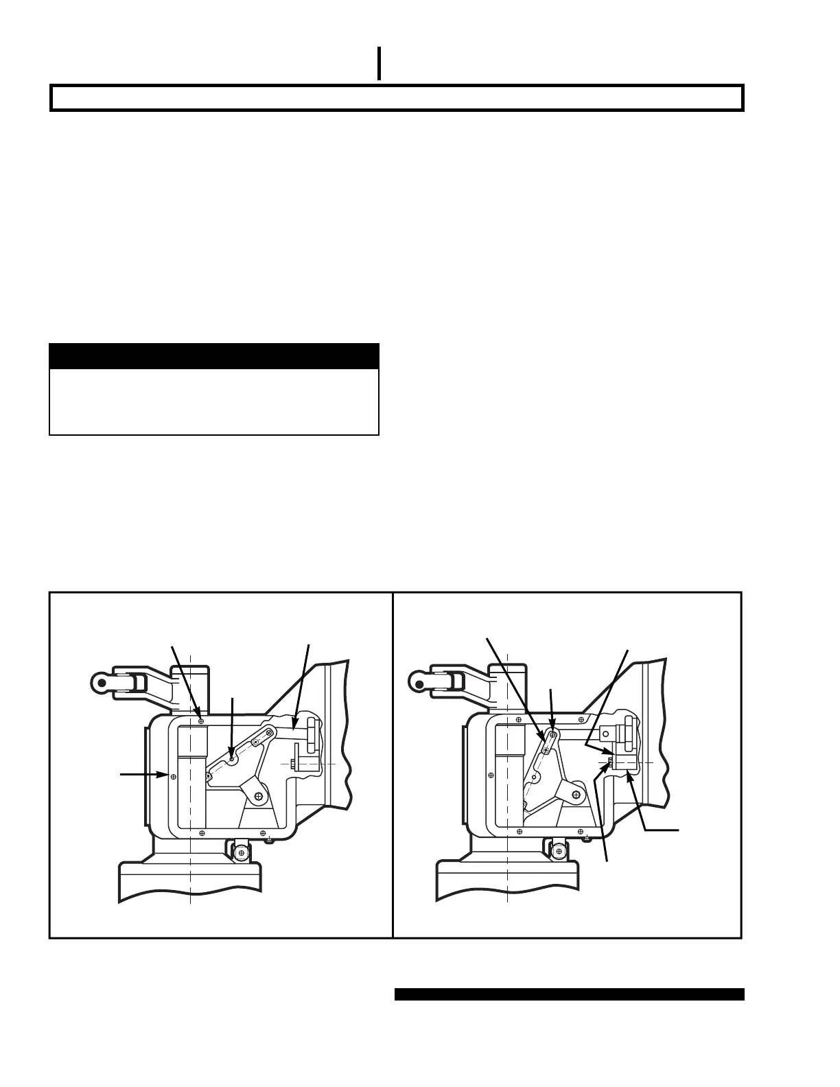
⁵⁄₁₆—182¹⁄₄ hex-head
stainless-steel screw
Transition lever in shipping position
Transition lever in open position
Spacer
(marked
with a
black/
yellow
striped
label)
Operating rod link
Transition
lever
⁵⁄₁₆—18³⁄₄ hex-head
stainless-steel cap screws for
access cover (removed)
Transition
box
Connecting pin
retainer
³⁄₈ stainless-
steel connect-
ing pin
Stop bracket (marked
with a black/yellow
striped label)
Figure 8. Preparing insulated operating rod for attachment.
 Loading...


