S&C ELECTRIC COMPANY
s
INSTRUCTION SHEET
716-501
Page 17 of 26
August 12, 2002
INSTALLATION — Continued
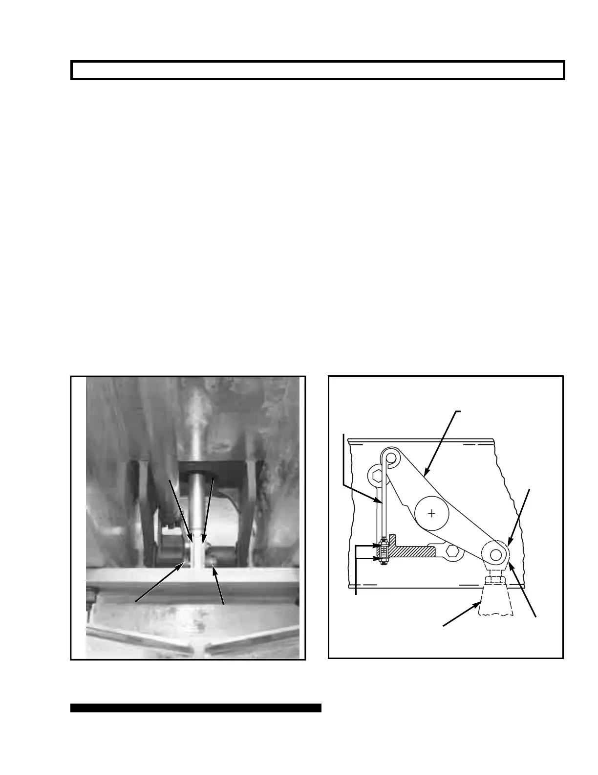
Adjustable locking rod
(marked with a black/yellow
striped label)
Interphase drive lever
¹⁄₄—20 locknut
Operator connecting link
³⁄₄ stainless-steel pin
and cotter pin
Uni-ball
coupling
Step 17
Attach the uni-ball coupling on the operator connecting
link to the interphase drive lever in the cross base, using
the ³⁄₄-inch stainless-steel pin and cotter pin retained from
Step 7. See Figure 10. An adjustable locking rod (marked
with a black/yellow striped label) is furnished, factory-con-
nected to the interphase drive lever; turn the associated
¹⁄₄—20 locknuts as required to raise or lower the inter-
phase drive lever and thus facilitate insertion of the stain-
less-steel pin.
Step 18
Remove the lower ¹⁄₄—20 locknut which retains the
adjustable locking rod. Then remove and discard the
adjustable locking rod and locknuts.
Figure 9. Attaching insulated operating rod to interphase
drive.
Insulated operating rod end links
Interphase drive
linkage lever
¹⁄₂ silicon-bronze
pin and cotter pin
Figure 10. Attaching connecting link to interphase drive
lever.
 Loading...


